

Initial design procedure of microstrip interdigital filter with tapped-line
-
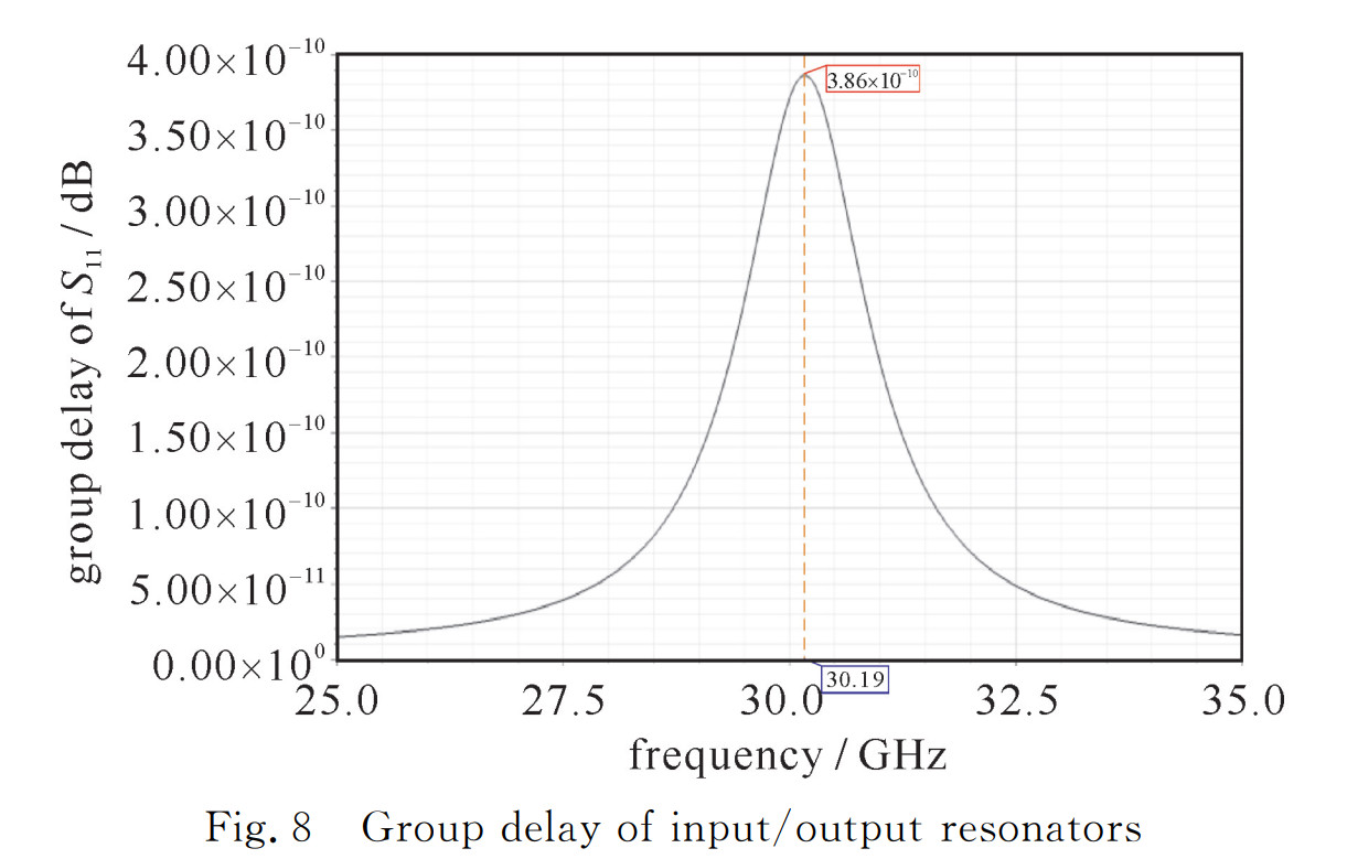
摘要: 带抽头的微带交指滤波器初始设计方法繁多,但设计不够全面、简洁,同时精度不高,因此给出了一套详细、简洁的初始设计流程。设计步骤为:指标“规范化”,确定低通原型滤波器,求解滤波器阶数,求解归一化电导值,设计抽头的线长和线宽,设计谐振器的线宽,设计非输入输出谐振器的线长,设计相邻谐振器间距,设计输入输出谐振器的线长和抽头的位置,交指滤波器整体建模仿真。最后以Ka波段滤波器为案例进行初始设计,初始设计结果显示中心频率在30.19 GHz附近,通带比29.40~31.00 GHz略大,通带内最大插入损耗为4.22 dB,最小回波损耗为9.32 dB,27.00 GHz和33.40 GHz的带外抑制大于30.00 dB,已经基本满足设计指标,后续只需要稍加优化就能完全满足设计指标,验证了此套设计流程的可行性及其较高的精度。Abstract: There are many initial design methods for microstrip interdigital filter with tapped-line but the design methods are not complate, concise and accurate enough, so a set of initial design flow with completeness and conciseness is given. The design steps are as follows: index "standardization", determine the low-pass prototype filter, determine the order of the filter, determine the normalized conductance value, design tapped line length and width, design resonator width, design non-input/output resonator length, design adjacent resonator spacing, design input/output resonator length and tapped line position, integral modeling and simulation of interdigital filter. Finally, taking the initial design of Ka-band filter as an example, the initial design results show that the center frequency is about 30.19 GHz, the passband range is slightly larger than 29.40-31.00 GHz, the maximum insertion loss is 4.21 dB, the minimum return loss is 9.35 dB, the stopband rejection of 27.00 GHz and 33.40 GHz is more than 30.00 dB, which basically meet the design indexes, only a little optimization is needed to fully meet the design indexes, and the feasibility and high accuracy of the design flow are verified.
-
Key words:
- MEMS /
- interdigital filter /
- microstrip line /
- tapped-line
-
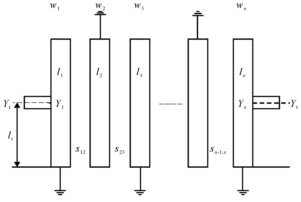
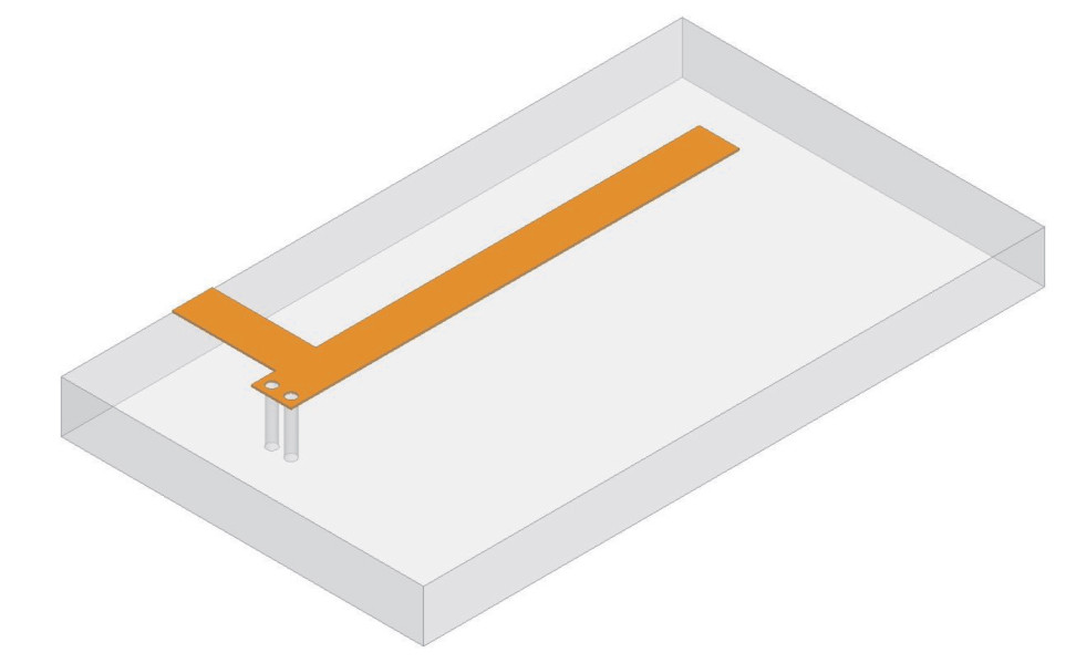
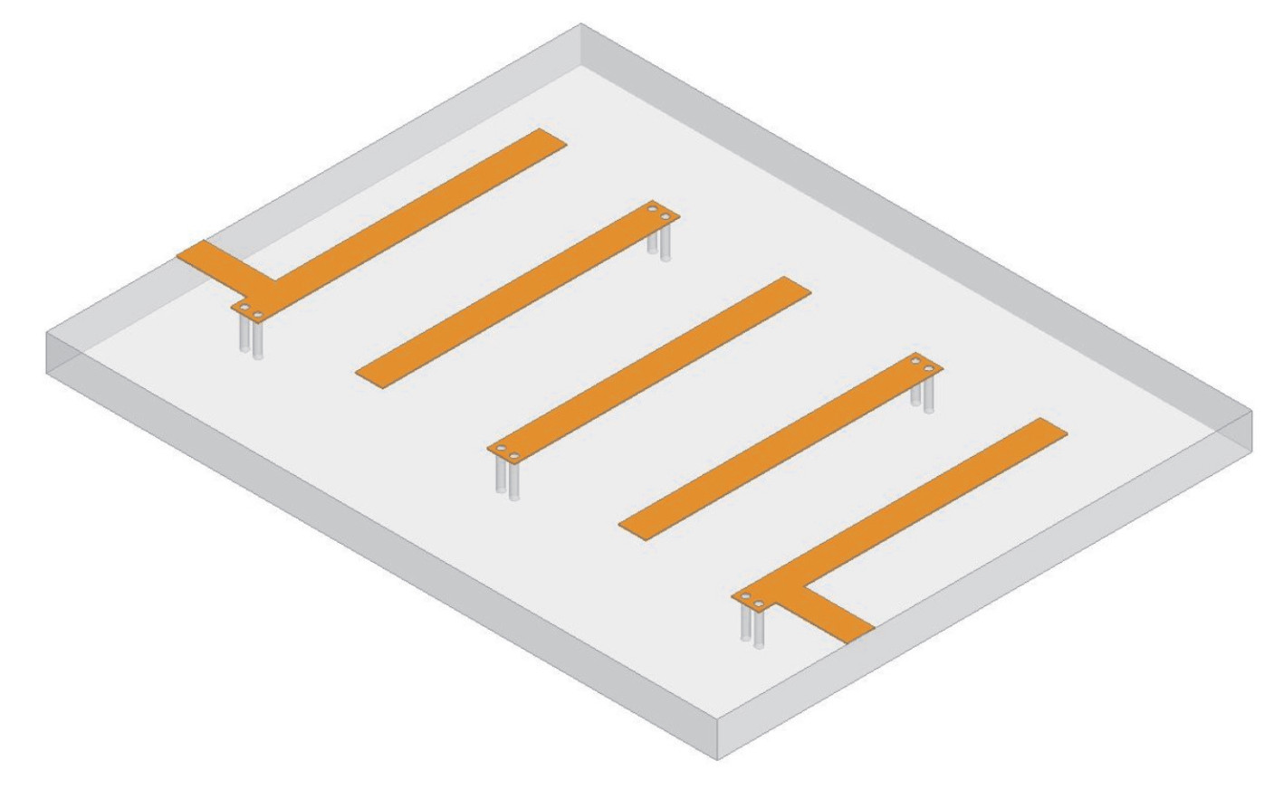
图 1 带抽头的微带交指滤波器一般模型
Figure 1. General configuration of interdigital filter with tapped-line
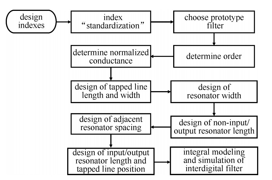
图 2 带抽头的微带交指滤波器初始设计流程
Figure 2. Initial design procedure of interdigital filter with tapped-line
表 1 滤波器设计指标
Table 1. Design specification of the filter
center frequency /GHz passband frequency range/GHz passband ripple /dB insertion loss /dB return loss /dB stop rejection /dB 30.19 29.4~31 1 2~3 17.7 ≥30@27 GHz&33.4 GHz  下载: 导出CSV
表 2 切比雪夫原型滤波器归一化电导值
Table 2. Normalized conductance value of the Chebyshev prototype filter
n g0 g1 g2 g3 g4 g5 g6 5 1 0.971 4 1.372 1 1.801 4 1.372 1 0.971 4 1
下载: 导出CSV
表 3 耦合系数m,k与谐振器间距s
Table 3. Coupling coefficient m, k and resonator spacing s
i m k s/mm 1~2 0.045 91 0.045 8 0.256 2~3 0.033 71 0.033 6 0.292 3~4 0.033 71 0.033 6 0.292 4~5 0.045 91 0.045 8 0.256
下载: 导出CSV
-
[1] Sahu B, Meshram M K, Singh S P, et al. Simulation study of modified compact microstrip interdigital bandpass filter with wide stopband for L-band applications[C]//IEEE MTT-S International Microwave and RF Conference. 2016: 409-411. [2] Chen C, Wu Q. Fast design and optimization of bandpass tapped-line interdigital filters using GENESYS[C]//IEEE China-Japan Joint Microwave Conference. 2008. 2009: 103-106. [3] 郑冬, 王志刚, 罗浚溢. 抽头式交指带通滤波器的设计及实现[C]//全国信息与电子工程学术年会. 2010.Zheng Dong, Wang Zhigang, Luo Junyi. Design of microstrip tapped-input interdigital bandpass filters//National Annual Conference on Information and Electronic Engineering. 2010 [4] 刘海强, 周立学, 李良. 交指型微带带通滤波器的设计[J]. 电子科技, 2014, 27(7): 71-73. https://www.cnki.com.cn/Article/CJFDTOTAL-DZKK201407021.htmLiu Haiqiang, Zhou Lixue, Li Liang. Design of a broad-band interdigital microstrip bandpass filter. Electronic Sci & Tech, 2014, 27(7): 71-73 https://www.cnki.com.cn/Article/CJFDTOTAL-DZKK201407021.htm [5] Wong J S. Microstrip tapped-line filter design[J]. IEEE Transactions on Microwave Theory & Techniques, 1979, 27(1): 44-50. [6] Chang K. Microstrip filters for RF/microwave applications[M]. 2nd ed. New Jersey: John Wiley & Sons Inc, 2011. [7] Matthaei G L. Interdigital, band-pass filters[C]//IEEE PGMTT National Symposium Digest. 1962: 41-45. [8] Caspi S, Adelman J. Design of combline and interdigital filters with tapped-line input[J]. IEEE Trans Microwave Theory & Techniques, 1988, 36(4): 759-763. [9] Chakravorty P, Das S, Mandal D, et al. Feed line optimization in pseudo-interdigital bandpass filters[C]//IEEE International WIE Conference on Electrical and Computer Engineering. 2016: 391-393. -


 点击查看大图
计量
- 文章访问数: 2121
- HTML全文浏览量: 445
- PDF下载量: 327
- 被引次数: 0
