Grounding via-hole effect pre-considered microstrip interdigital filter design
-
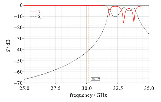
摘要: 微带交指滤波器通常需要使用接地孔接地,传统的设计方法是在整体建模时再考虑接地孔的影响,导致了接地孔的个数、大小、位置都不确定的多因素、多水平问题,因此可以在设计过程中提前考虑接地孔的影响来避免这些问题。以Ka波段滤波器为案例,分别使用了传统的奇偶模阻抗法、耦合系数和外部品质因数法以及在设计过程中考虑了接地孔的改进方法进行设计。初始设计结果显示,传统方法的中心频率发生偏移,并且其他参数与设计指标相差甚远,而改进方法的中心频率、通带范围以及带外抑制满足指标要求,并且最大插入损耗为3.08 dB,最小回波损耗为10.08 dB,有利于减少后续迭代次数。Abstract: Via-holes are usually required to ground for microstrip interdigital filter.The influence of the grounding via-hole is considered when modeling the overall system in traditional design methods, which will lead to the multi-factor and multi-level problem since the number, size and position of the grounding via-holes are uncertain.The problems can be avoided by proposing grounding via-hole effect in microstrip interdigital filter design.Taking Ka-band filter as an example, the traditional odd-even mode impedance method, coupling coefficient and external quality factor method, and the modification method of considering the grounding via-holes in the design process are used to design the filter respectively.The initial design results show that the center frequency of the traditional method is shifted to the left, and other parameters are much different from the design specification.The center frequency, passband range and stop rejection of the modification method meet the requirements of the specification, and the maximum insertion loss is 3.08 dB, the minimum return loss is 10.08 dB, which is helpful to reduce the subsequent iterations.
-
Key words:
- MEMS /
- filter /
- interdigital /
- microstrip line /
- grounding via-hole /
- design
-
表 1 滤波器设计指标
Table 1. Design specification of the filter
center frequency/GHz passband frequency range/GHz passband ripple/dB insertion loss/dB return loss/dB stop rejection/dB 30.19 29.4~31 1 2~3 17.7 ≥30@27 GHz&33.4 GHz 表 2 交指滤波器的奇偶模阻抗值
Table 2. Even and odd mode impedances of the interdigital filter
i Z0ei, i+1 Z0oi, i+1 1 51.80 48.20 2 51.29 48.65 3 51.29 48.65 4 51.80 48.20 表 3 交指带通滤波器的奇偶模相对介电常数和间距
Table 3. Even and odd mode relative dielectric constants and spacing of the interdigital bandpass filter
i εreie εreio si, i+1/mm 1 7.999 7.784 1.066 3 2 7.981 7.821 1.394 2 3 7.962 7.857 1.394 2 4 7.981 7.821 1.066 3 5 7.999 7.784 — 表 4 耦合系数M,K与谐振器间距s
Table 4. Coupling coefficients M, K and resonator spacing s
i M K s/mm 1~2 0.045 91 0.046 1 0.645 2~3 0.033 71 0.033 8 0.75 3~4 0.033 71 0.033 8 0.75 4~5 0.045 91 0.046 1 0.645 -
[1] Tang B, Cao Q. Effects of relative position errors of grounding holes on the performances of interdigital bandpass filters[C]//IEEE Cross Strait Quad-Regional Radio Science and Wireless Technology Conference. 2013: 43-46. [2] 张娜, 李元. 接地金属化孔对交指带通滤波器频响的影响分析[J]. 中国电子科学研究院学报, 2011, 6(5): 548-550. doi: 10.3969/j.issn.1673-5692.2011.05.024Zhang Na, Li Yuan. Analysis of grounding via holes influenced the frequency response of interdigital bandpass filter. Journal of China Academy of Electronics and Information Technology, 2011, 6(5): 548-550 doi: 10.3969/j.issn.1673-5692.2011.05.024 [3] Swanson D G J. Grounding microstrip lines with via holes[J]. IEEE Trans Microwave Theory & Techniques, 1992, 40(8): 1719-1721. [4] Chen C, Wu Q. Fast design and optimization of bandpass tapped-line interdigital filters using GENESYS[C]//IEEE Microwave Conference, 2008 China-Japan Joint. 2009: 103-106. [5] 王义, 楚光辉. 一种微带交指型滤波器的改良型设计[J]. 无线电工程, 2007, 37(12): 34-36. https://www.cnki.com.cn/Article/CJFDTOTAL-WXDG200712011.htmWang Yi, Chu Guanghui. Design of an improved microstrip interdigital filter. Radio Engineering, 2007, 37(12): 34-36 https://www.cnki.com.cn/Article/CJFDTOTAL-WXDG200712011.htm [6] 刘海强, 周立学, 李良. 交指型微带带通滤波器的设计[J]. 电子科技, 2014, 27(7): 71-73. https://www.cnki.com.cn/Article/CJFDTOTAL-DZKK201407021.htmLiu Haiqiang, Zhou Lixue, Li Liang. Design of a broad-band interdigital microstrip bandpass filter. Electronic Sci & Tech, 2014, 27(7): 71-73 https://www.cnki.com.cn/Article/CJFDTOTAL-DZKK201407021.htm [7] 陈松, 钟朝位, 刘稷, 等. 陶瓷基交指微带带通滤波器的设计[J]. 电子元件与材料, 2017, 36(1): 48-50. https://www.cnki.com.cn/Article/CJFDTOTAL-DZAL201701009.htmChen Song, Zhong Chaowei, Liu Ji, et al. Design of an interdigital microstrip bandpass filter on ceramic substrate. Electronic Components and Materials, 2017, 36(1): 48-50 https://www.cnki.com.cn/Article/CJFDTOTAL-DZAL201701009.htm [8] 文数文, 高杨, 许夏茜. 带抽头的微带交指滤波器初始设计流程[J]. 强激光与粒子束, 2018, 30: 074101. doi: 10.11884/HPLPB201830.180007Wen Shuwen, Gao Yang, Xu Xiaxi. Initial design procedure of microstrip interdigital filter with tapped-line. High Power Laser and Particle Beams. 2018, 30: 074101 doi: 10.11884/HPLPB201830.180007 [9] Goldfarb M E, Pucel R A. Modeling via hole grounds in microstrip[J]. IEEE Microwave & Guided Wave Letters, 1991, 1(6): 135-137. [10] Chang K. Microstrip filters for RF/microwave applications[M]. 2nd. New Jersey: John Wiley & Sons Inc, 2011. [11] Caspi S, Adelman J. Design of combline and interdigital filters with tapped-line input[J]. IEEE Trans Microwave Theory & Techniques, 1988, 36(4): 759-763. [12] Denig C. Using microwave CAD programs to analyze microstrip interdigital filters[J]. Microwave Journal, 1989, 32(3): 147-152. [13] 郑冬, 王志刚, 罗浚溢. 抽头式交指带通滤波器的设计及实现[C]//全国信息与电子工程学术年会. 2010.Zheng Dong, Wang Zhigang, Luo Junyi. Design of microstrip tapped-input interdigital bandpass filters//National Annual Conference on Information and Electronic Engineering. 2010 -


 下载:
下载:


