Design and implementation of acquisition monitoring system for static magnetic field testing platform
-
摘要: 介绍了静态磁场测试平台的结构和特点,详细描述了采集监控系统的体系架构,该系统是由数据采集管理系统和操作监控平台组成的。根据该系统的特点,设计了基于Qt的数据采集管理系统和基于EPICS的操作监控平台。该系统实现了对静态磁场测试平台的实时控制、设备状态检测及监控、数据采集、存储及查看。该应用运行稳定,能满足静态磁场测试平台对采集监控的需求。Abstract: This paper introduces the architecture and characteristics of the static magnetic field testing platform, and describes the architecture of the acquisition monitoring system, which is composed of data acquisition management system and operation monitoring platform. According to the characteristics of the system, a data acquisition management system based on Qt and an operation monitoring platform based on EPICS are designed. The system realizes real-time control of static magnetic field testing platform, equipment status detection and monitoring, data acquisition, storage and inspection. The application runs stably and can meet the requirements of the static magnetic field testing platform for acquisition and monitoring.
-
随着磁约束聚变研究的发展,托卡马克装置运行参数越来越高,等离子体电流即将达到MA级别。如此高的等离子体电流将在托卡马克装置周围产生极强的空间磁场;另外在等离子体破裂过程中,等离子体电流迅速衰减,将在其周围产生极高的瞬变磁场。如此高的磁场将会影响主机大厅中的测控、电源、诊断、水冷和主机内部部件等聚变装置相关的部件和系统的稳定运行,进而影响其系统的运行稳定性与可靠性[1-2]。为了提供托卡马克装置相关部件与系统在高强度稳态及瞬变磁场环境下的电磁兼容性研究和测试,中国科学院等离子体物理研究所研制设计了一套标称磁场强度达60 mT的静态磁场测试平台,静态磁场测试发生线圈尺寸为2.1 m×2.1 m×2.1 m的正方体结构。静态磁场测试平台是由电源系统,测试线圈,水冷系统和其他辅助系统构成的。本文设计了一种多通道高精度同步的采集监控系统。该系统由数据采集管理系统和操作监控平台组成。数据采集管理系统负责采集分布在测试空间上的上百个点的磁场场强,并实现存储及事后查看;操作监控平台实现对静态磁场测试平台的电源的启停控制,状态检测及监控。
1. 总体方案设计
静态磁场测试平台的核心子系统由静态磁场发生线圈、直流电源系统和控制系统组成。如图 1所示,直流电源系统主要为线圈系统提供稳定、可控的直流电流,输出电流误差及波动峰-峰值(包括输出波动及纹波)不超过目标测试电流的5%。我们采用的是大功率直流稳态测试平台电源[3]。该电源是由两套变流器并联运行,单套变流器输出电压1050 V、最大输出电流30 kA。并联运行后输出电流为12脉波,输出电流0~60 kA电流可调,电流稳定度≤2%(峰峰值和平均值之比)。
静态磁场测试平台的直流电源系统是利用已有的大功率测试平台的稳态直流电源作为其供电系统,因此静态磁场测试平台的控制系统包括2大部分:直流电源控制系统和采集监控系统。大功率测试平台稳态直流电源的控制系统可以实现稳态电源的电流/电压预设、电流/电压控制、电流差动和过流保护等功能;采集监控系统实现对静态测试平台的数据采集存储以及现场信号监控,这是本论文的重点研发对象。
2. 采集监控系统
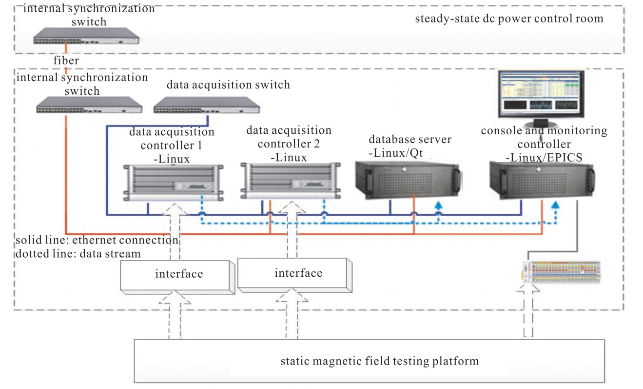
静态磁场测试平台的采集监控系统是由2个独立的子网组成的,分别是:内部同步网和数据采集网,其体系结构如图 2所示。采集监控系统和直流电源控制系统之间的内部同步交换机通过光纤级联,并且互相之间进行数据交互,主要是传输炮号等数据包;采集监控系统内部的计算机之间通过数据采集网进行数据传输和管理。
静态磁场测试平台的采集监控系统主要包括数据采集管理系统和操作监控平台。数据采集管理系统负责采集静态磁场测试平台的测试线圈的多个空间区域的磁场场强并存储,同时在固定的周期内将各采集点的磁场场强传输至操作监控平台进行实时显示;操作监控平台负责启停直流电源,采集静态磁场线圈的水冷状态,实时显示以及状态报警。
2.1 数据采集管理系统
2.1.1 体系结构
静态磁场测试平台的数据采集管理系统是由2台数据采集计算机和一台数据库服务器组成的,其体系结构如图 3所示。静态磁场内测试空间划分为上百个区域,每个区域内安装一维磁场探头一个,测量对应空间内磁场强度。此上百个采样点数据由采集计算机负责完成;数据库服务器负责管理采集系统和存储系统的时序,配置采集计算机的采集卡信息和采样频率,发送采集计算机启动/停止采集命令,并将采集计算机的采集数据以脉冲树的方式进行存储,方便事后数据查看分析。
2.1.2 体系结构
本论文中的数据采集管理系统采用外部触发和外部时钟实现2台采集计算机的时间同步,数据库服务器接收到外部采集触发信号后通过时间同步卡PCI-8554发送设定的外部时钟频率和启动/停止采集命令,这样可以保证采集系统中的每块采集卡具有相同的参考时钟频率,当外部启动采集命令到达,所有的采集卡开始触发采集收集数据。采集计算机在固定周期内将数据打包发送至数据库服务器,由数据库利用分片机制存储数据。
(1) 控制台的实现
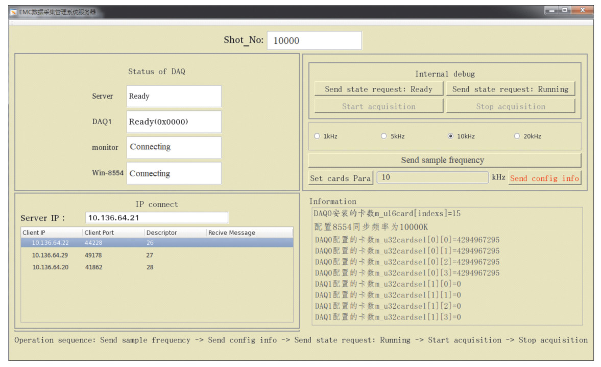
数据库服务器的应用程序是基于Qt软件进行开发的。Qt是一个带有跨平台架构的C++GUI应用程序,用于开发控制台和服务器等[4-5]。数据库管理系统开发了一个方便操作管理的控制台,如图 4所示,该控制台可以直观地实时显示当前数据采集网内的计算机状态,可以在线配置采集计算机采集卡的起始通道号,信号名,采集通道数以及采样率等。
(2) 状态机的控制
数据库服务器和采集计算机的程序都是独立运行的,如果按照各自的时序运行,当有程序运行过程中出现故障时将很难被发现,所以为了保证数据库服务器和多台数据采集计算机按照一定的时序运行,数据库管理系统开发了一个有序的状态机管理。每个运行过程对应一个状态,当满足一定条件时就向下一个状态转变,每个过程会包括相应的执行步骤,这些步骤只能在当前状态执行。数据管理系统定义了四种状态:Initial,Ready,Running和Fault,如表 1所示。当程序运行后,开始初始化操作,初始化成功后进入Ready状态。然后数据库服务器发送配置信息给采集程序;采集程序的配置成功返回信息,进入Running状态。当接收到炮号时,数据库服务器创建脉冲树,当接收到外部触发采集脉冲信号时生成内部触发高电平,触发数据采集,采集数据存储到数据库。
表 1 数据管理系统状态定义表Table 1. Data management system status definition tablestatus database server DAQ computer initial · Initialize database; · Initialize resources; · Initialize monitoring interface; · Report database server AD cards resources; · After successful initialization, system will automatically enter running state. · After initialization, DAQ automatically enter the ready state. ready · Set the configuration information of AD cards, then sent to the DAQs; · AD cards is configured according to the database configuration information frame. The condition of AD cards is ready and DAQ enters running state. · Set AD cards sampling frequency; · Waiting for the successfully configured information frame of the AD cards, then system entered running state. running · Wait for other shots and stop/start frames; · By external trigger level control DAQs start and stop; · After the above information is collected, send it to the DAQ computers and wait to receive the collected data; · After receiving the command to reconfigure the AD cards from the database server, system stops acqusition, releases resources and enters into the ready state. · Wait for external pulse for trigger acquisition to generate internal high level; · To reconfigure the AD cards, send Ready request to the DAQ computers, and the trigger signal turns to low level, waiting for the DAQ computers to return their state and then system enters to ready state. fault · Manually check the fault cause of the server or the DAQ computers, and troubleshoot the failure and
back to the initial state.(3) 数据库存储的实现
由于静态磁场测试平台的实验数据是以炮号收集数据,每次实验产生的数据都是一个根据时序排列的矢量数据集合,数据量都比较大,数据长度不固定,实时存储;需要在线访问这些数据,而且只对实验过程中某个时间段感兴趣。因此采用MDSplus作为静态磁场测试平台存储数据的数据库开发软件。
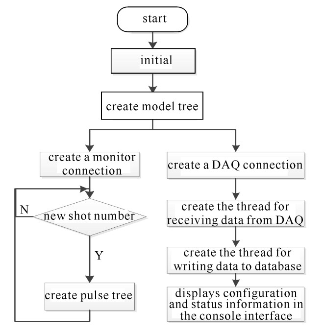
MDSplus (Model Drive System plus)是一个通用的集数据采集、数据存储、数据分析、数据可视化等多功能为一体的软件系统,具有模型驱动的数据库系统,主要适用于大型核聚变实验装置[6]。MDSplus数据库采用树形层次结构来组织每次通电的实验数据,每一炮数据单独构成一个数据文件(扩展名为datafile),各炮数据间没有关联性,这样可使数据文件的存储结构变得更加统一[7]。因此,本文采用MDSplus数据库来存储这些脉冲数据。如图 5所示,首先初始化创建模型树;等待外部发送新炮号,再创建脉冲树;创建采集计算机连接,创建接收线程和数据写入数据库线程,并且在控制台显示配置信号和数据采集网内的计算机状态。
2.2 操作监控平台
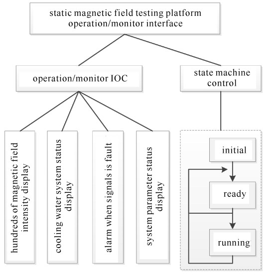
操作监控平台是静态磁场测试平台的核心子系统,如图 6所示,操作监控计算机是其核心计算机,采用工业用控制计算机为硬件平台,配置2块千兆以太网卡和一块数字量输入输出DIO卡。外部信号的输入和输出通过光信号进行转接,以实现电信号的隔离;和外部的数据交互分别通过两块千兆以太网卡实现:和数据采集网交互磁场场强等信号,和现场总线交互水冷系统的信号。操作监控平台的主要功能是采集监测显示水冷系统状态,显示静态磁场各区间的磁场场强;实现静态磁场测试平台系统状态转换和电源启停控制命令。
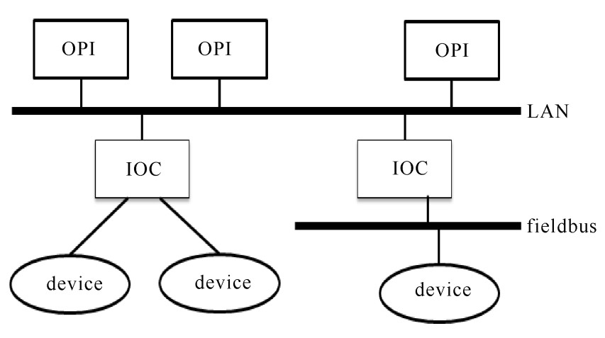
操作监控平台的应用程序选择实验物理和工业控制系统EPICS(experimental physics and industrial control system)作为其开发工具。EPICS是由美国洛斯·阿拉莫斯国家实验室和阿贡国家实验室等联合开发的典型的分布式控制系统软件开发工具[8]。EPICS控制系统采用称为“标准模型”的分布式控制体系结构如图 7所示,由操作员接口计算机(Operator interface, OPI)、输入输出控制器(I/O controller, IOC)、设备控制器(Device controller)三个层次组成,具有运行稳定、系统结构灵活、开放性好、可扩展性好、国际交流协作方便等诸多优点;同时大量工具都是免费的且提供技术支持, 现已逐渐成为国际核聚变装置控制系统的一个主流的软件开发工具[9]。
操作监控计算机和水冷系统的现场总线控制器通过直连的方式,采用Modbus/TCP协议实现交换数据。现场总线控制器采集的信号分别为16路水压,16路水温和16路水流量,共计48路数字量信号;3路模拟量信号,分别为总进水流量,总进水温度和总进水压力。另外操作监控计算机和数据采集网通过TCP/IP协议和数据库服务器进行数据交互:发送炮号等数据包,周期性地接收上百路静态磁场场强信号。操作监控计算机应用软件采用EPICS的设备/驱动支持程序(Device/driver support)实现和输入输出控制器IOC的信号转换,将水冷系统信号和磁场场强信号转换为EPICS软件的过程变量,保证能实时可靠地在人机界面上显示,实现信号状态的监测和报警。
为了保证静态磁场测试平台在实验过程中能有效可靠地按照一定的时序运行,操作监控计算机设计了四个状态:初始化、就绪、工作、故障,如表 2所示。在该系统中使用SNL开发状态机程序,与C语言类似,便于编写顺序操作相关的程序。
表 2 静态磁场测试平台状态定义表Table 2. Static magnetic field testing platform status definition tablestatus definition initial · Initializing the monitoring interface, the static magnetic field testing platform does not work, and the power supply is in the shutdown state. Initialization state. ready · The static magnetic field testing platform system and the power supply system is normal; · Send the signals to the database; · Enter to ready state. running · Send the starting signal to the power system and wait for the power supply to be turned on; · Send trigger DAQ signal to the database; · The working state of power supply enters the ready state; · The static magnetic field testing platform is in normal condition; · Enter to running state. fault · The power status is in fault; · Static magnetic field testing platform state is in fault. EPICS用户软件的人机界面由运行了EPICS的客户端采用基于Eclipse工具包的CSS(Control System Studio)工具实现人机交互界面的开发[10]。如图 8所示,客户端通过通道协议CA访问操作监控计算机的EPICS节点,读取数据库的过程变量PV,显示相关的信号状态;当实验中出现故障时,可以在人机界面上显示详细的信号名,故障描述,故障触发时刻,当前严重度,以及故障原因和解决办法;并实时显示当前故障是否解除。
3. 实验和结果
该测试平台于2018年5月初搭建成功,并进行了第一轮通电实验。在测试空间中,安排了10个磁场测量点。根据试验程序,分别测量了10个测量点的磁场强度,如图 9所示,在稳态电流30 kA(图 9(a))时,磁场场强在100 B/mT左右(图 9(b))。
实验结果表明,静态磁场测试平台的采集监控系统能够稳定可靠运行,功能完善,操作简单;有效地实现了数据备份,提高了数据的安全性,很好满足了静态测试平台的数据管理和系统运行中状态过程的分析需求。
4. 结论
静态磁场测试平台的采集监控系统采用Qt作为数据管理系统的开发软件,实现了有序地对静态磁场测试平台上百个采样点的数据采集、存储和管理;采用EPICS作为操作监控平台的系统开发软件,实现了对静态磁场测试平台的水冷系统的状态监测及显示,实时显示静态磁场各区间的磁场场强,以及实现静态磁场测试平台系统状态转换和电源启停控制命令。该系统已通过实验平台测试验证,能够满足静态测试平台的采集监控系统的设计要求,证实了该方案的可行性,是稳定可靠的。
-
表 1 数据管理系统状态定义表
Table 1. Data management system status definition table
status database server DAQ computer initial · Initialize database; · Initialize resources; · Initialize monitoring interface; · Report database server AD cards resources; · After successful initialization, system will automatically enter running state. · After initialization, DAQ automatically enter the ready state. ready · Set the configuration information of AD cards, then sent to the DAQs; · AD cards is configured according to the database configuration information frame. The condition of AD cards is ready and DAQ enters running state. · Set AD cards sampling frequency; · Waiting for the successfully configured information frame of the AD cards, then system entered running state. running · Wait for other shots and stop/start frames; · By external trigger level control DAQs start and stop; · After the above information is collected, send it to the DAQ computers and wait to receive the collected data; · After receiving the command to reconfigure the AD cards from the database server, system stops acqusition, releases resources and enters into the ready state. · Wait for external pulse for trigger acquisition to generate internal high level; · To reconfigure the AD cards, send Ready request to the DAQ computers, and the trigger signal turns to low level, waiting for the DAQ computers to return their state and then system enters to ready state. fault · Manually check the fault cause of the server or the DAQ computers, and troubleshoot the failure and
back to the initial state.表 2 静态磁场测试平台状态定义表
Table 2. Static magnetic field testing platform status definition table
status definition initial · Initializing the monitoring interface, the static magnetic field testing platform does not work, and the power supply is in the shutdown state. Initialization state. ready · The static magnetic field testing platform system and the power supply system is normal; · Send the signals to the database; · Enter to ready state. running · Send the starting signal to the power system and wait for the power supply to be turned on; · Send trigger DAQ signal to the database; · The working state of power supply enters the ready state; · The static magnetic field testing platform is in normal condition; · Enter to running state. fault · The power status is in fault; · Static magnetic field testing platform state is in fault. -
[1] Yang Y, Zhang M, Song Z, et al. Stray magnetic field analysis of ITER poloidal field converter unit[J]. IEEE Tran Plasma Science, 2017, 45(3): 495-500. doi: 10.1109/TPS.2017.2655264 [2] Yang Y, Zhang M, Yu K, et al. Electromagnetic compatibility analysis and design of ITER poloidal field converter unit[C]//IEEE Fusion Engineering. 2016: 1-6. [3] 邝凡. ITER直流测试平台整流器均流结构优化及动稳定校核[D]. 北京: 中国科学院大学, 2016.Kuang Fan. The structure optimization and dynamic stability check of the rectifier on ITER dc testing platform. Beijing: University of Chinese Academy of Sciences, 2016 [4] Qt reference documentation[EB/OL]. http://doc.qt.io/qt-5/referenceoverview.html. [5] Zhu L, Huang L, Fu P, et al. Upgrade of the synchronous data management system of the EAST poloidal field power supply[J]. Fusion Engineering & Design, 2016, 112: 218-224. [6] MDSplus documentation library[EB/OL]. http://www.MDSplus.org. [7] 张永定, 秦品健, 郑锐. MDSplus在EAST极向场电源数据管理系统中的应用[J]. 电源技术, 2011, 35(8): 966-968. doi: 10.3969/j.issn.1002-087X.2011.08.025Zhang Yongding, Qin Pinjian, Zheng Rui. Application of MDSplus in data management of EAST poloidal field power supply. Chinese Journal of Power Sources, 2011, 35(8): 966-968 doi: 10.3969/j.issn.1002-087X.2011.08.025 [8] ANL. What is EPICS?[EB/OL]. https://wiki-ext.aps.anl.gov/epics/index.php/EPICS_FAQ. [9] 何诗英, 黄连生, 高格, 等. 实验物理和工业控制系统在极向场电源控制系统中的应用[J]. 强激光与粒子束, 2017, 29: 026001. doi: 10.11884/HPLPB201729.160436He Shiying, Huang Liansheng, Gao Ge, et al. Application of experimental physics and industrial control system in poloidal field power supply control system. High Power Laser and Particle Beams, 2017, 29: 026001 doi: 10.11884/HPLPB201729.160436 [10] 郭凤琴, 赵卓, 王春红. CSS BOY在BEPCⅡ控制系统中的应用[J]. 信息与电脑: 理论版, 2013(3): 1-3. https://www.cnki.com.cn/Article/CJFDTOTAL-XXDL201306002.htmGuo Fengqin, Zhao Zhuo, Wang Chunhong. Application of CSS BOY in BEPCⅡ control system. China Computer & Communication, 2013(3): 1-3 https://www.cnki.com.cn/Article/CJFDTOTAL-XXDL201306002.htm 期刊类型引用(6)
1. 汤东. 大数据运作平台下的植保机作业布局研究. 农机化研究. 2021(03): 254-259 .  百度学术
百度学术2. 杨浩,闫二艳,郑强林,鲍向阳,胡海鹰. S波段速调管微波源测控一体化及输出特性. 太赫兹科学与电子信息学报. 2021(01): 71-74 .  百度学术
百度学术3. 张志勇,孔令刚,范多进,姚小明. 太阳能电站集热岛数据采集及监控系统的实现. 兰州交通大学学报. 2021(02): 66-73 .  百度学术
百度学术4. 刘阳. 对抗性虚拟仿真网络支持下立体多动画显示平台设计. 现代电子技术. 2021(16): 145-149 .  百度学术
百度学术5. 赵莹,池葆春. 基于CAN总线技术的市场运营数据采集器设计. 自动化与仪器仪表. 2020(09): 119-122 .  百度学术
百度学术6. 钟建栩,朱磊,余少峰,佘俊,钟保强. 基于异常点检测的电能量信息采集与监控系统设计. 电子设计工程. 2020(21): 136-139+144 .  百度学术
百度学术其他类型引用(3)
-


 下载:
下载:


 下载:
下载:
