PCIe electromagnetic interference analysis and optimization design based on co-simulation of field and circuit
-
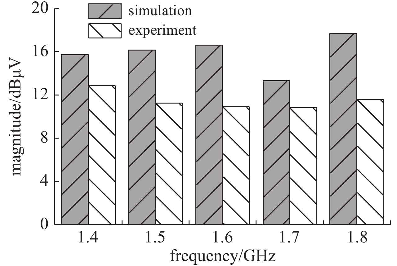
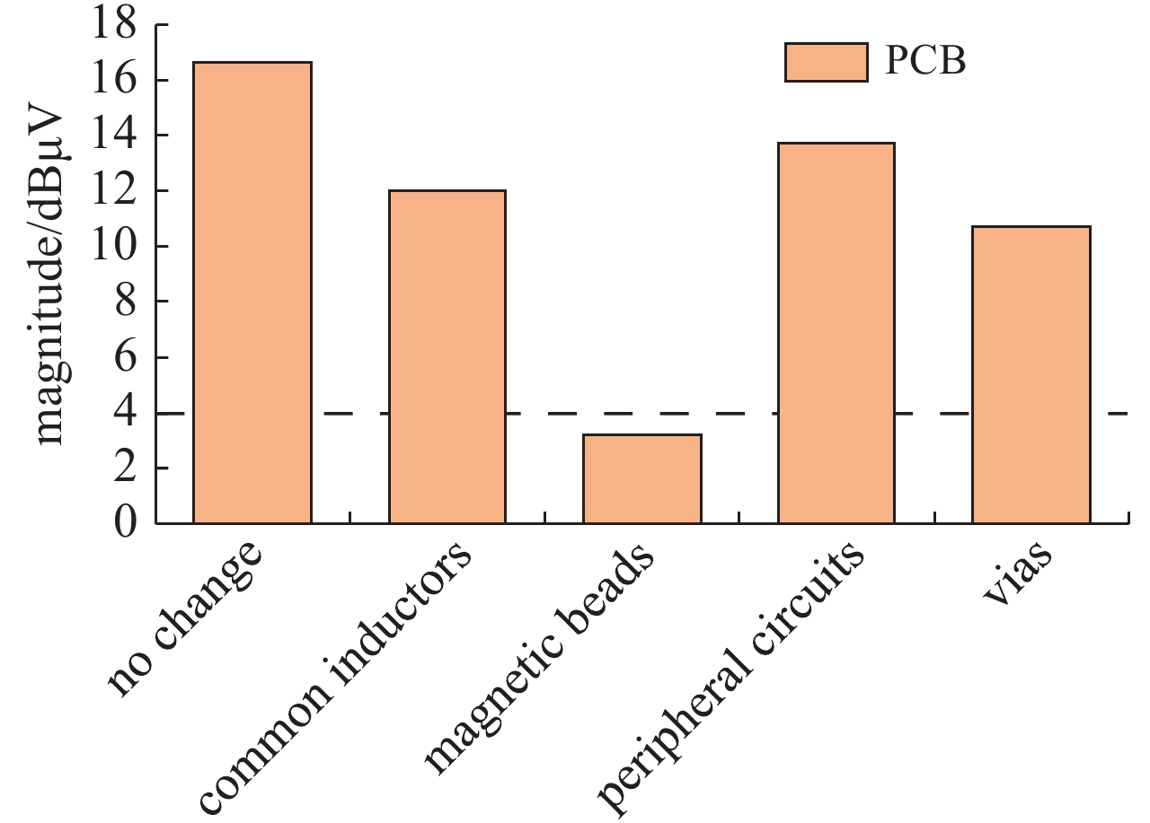
摘要: 采用电磁仿真技术,提前评估PCB的电磁兼容设计是否合理,当对PCB进行电磁兼容测试时,减少其电磁干扰不满足GMW 3097标准的情况出现。首先对PCB进行3D电磁场仿真,再与高速串行计算机扩展总线标准模块内芯片的通用模拟电路仿真模型的电路仿真动态链接,进行场路协同仿真。实验验证表明,该仿真方法的精度在6 dBμV之内,满足PCB加工工艺的误差和实验测试的不确定度,符合仿真精度要求。通过该仿真方法评估PCB的电磁干扰强度以及优化PCB的设计,将高速串行计算机扩展总线标准模块上的33 Ω电阻替换为磁珠后,该PCB在1.6 GHz处的电磁干扰强度降低了13.4 dB。根据CISPR 25标准规定的1-m法进行测试,PCB的电磁干扰变为−3.4 dBμV,低于GMW 3097标准要求,从而验证了该措施的有效性。
-
关键词:
- PCIe模块 /
- 共模辐射 /
- 电磁干扰 /
- 通用模拟电路仿真模型 /
- 电磁仿真
Abstract: In this paper, the rationality of Electromagnetic Compatibility(EMC)design of Printed Circuit Board (PCB) is evaluated in advance through electromagnetic simulation. The purpose of this method is to reduce the chances that the Electromagnetic Interference (EMI) of PCB does not meet GMW 3097 standard in EMC test. Firstly, the 3D electromagnetic field simulation of the Peripheral Component Interconnect express (PCIe) module on the PCB is performed. Then the field simulation is dynamically linked with the circuit simulation of the Simulation Program with Integrated Circuit Emphasis (SPICE) model of chip on the PCIe module, so that the co-simulation of field and circuit is performed. According to the experimental test, the accuracy of this simulation method is within 6 dBμV, which satisfies the deviation of PCB processing technology and the uncertainty of the experimental test. Thus, this simulation method meets the accuracy requirements. Therefore, the EMI of PCB can be evaluated and the PCB design can be optimized by this simulation method. After the 33 Ω resistors on the PCIe module was replaced by magnetic beads, the EMI of the PCB at 1.6 GHz is reduced by 13.4 dB. According to the 1-m method specified in the CISPR 25 standard for testing, the EMI of PCB becomes −3.4 dBμV, which is lower than the GMW 3097 standard requirement. Therefore, the effectiveness of this measure is verified. -
表 1 GMW 3097标准中对EMI的要求
Table 1. The EMI requirements for the GMW 3097 standard
name frequency/MHz EMI limit GPS 1 567 − 1 574 linearly decreased from 44 dBμV to 4 dBμV 1 574 − 1 576 4 dBμV 1 576 − 1 583 linearly increased from 4 dBμV to 44 dBμV GLONASS 1 598 − 1 606 4 dBμV -
[1] Veropoulos G P, Papakanellos P J, Vlachos C. A probabilistic approach for the susceptibility assessment of a straight PCB trace excited by random plane-wave fields[J]. IEEE Trans Electromagn Compat, 2018, 60(1): 258-265. doi: 10.1109/TEMC.2017.2704911 [2] Shantala, Sudheer M L. Analysis of electromagnetic interference radiations from the PCB traces[C]//International Conference on Recent Trends in Electrical, Control and Communication. 2018: 74-78. [3] Huang C Y, Chen C H, Greene C. Using parametric design to reduce the EMI of electronics products—example of medical-grade touch panel computer[J]. Prog Electromagn Res C, 2019, 89(1): 13-26. [4] Tang Qiu, Wang Yaonan, Christopoulos C. Simulation and research of the PCB vias effects[C]//International Conference on Natural Computation. 2007: 110-114. [5] Pan S, Fan J. Characterization of via structures in multilayer printed circuit boards with an equivalent transmission-line model[J]. IEEE Trans Electromagn Compat, 2012, 54(5): 1077-1086. doi: 10.1109/TEMC.2012.2187664 [6] Archambeault B, Brench C, Connor S. Review of printed-circuit-board level EMI/EMC issues and tools[J]. IEEE Trans Electromagn Compat, 2010, 52(2): 455-461. doi: 10.1109/TEMC.2010.2044182 [7] Carobbi C F M, Izzo D. Evaluation and improvement of the reproducibility of CISPR 25 ALSE test method[J]. IEEE Trans Electromagn Compat, 2018, 60(4): 1069-1077. doi: 10.1109/TEMC.2017.2780220 [8] IEC CISPR 25, Vehicles, boats and internal combustion engines—radio disturbance characteristics—limits and methods of measurement for the protection of on-board receivers[S]. 2015. [9] GMW 3097, General specification for electrical/electronic components and subsystems, electromagnetic compatibility[S]. 2015. [10] 赵阳, 颜伟, 赵波, 等. 电路辐射干扰机理诊断与特性估计[J]. 电工技术学报, 2010, 25(10):6-13. (Zhao Yang, Yan Wei, Zhao Bo, el at. EMI radiated noise diagnosis and estimation for HF circuits[J]. Transactions of China Electrotechnical Society, 2010, 25(10): 6-13 [11] 邱剑. 差分线对的PCB设计要点[J]. 通信技术, 2010, 43(6):221-223. (Qiu Jian. Essentials of differential pairs in PCB design[J]. Communications Technology, 2010, 43(6): 221-223 doi: 10.3969/j.issn.1002-0802.2010.06.076 [12] 赵志超. 高速差分传输线模型的分析与设计[D]. 西安: 西安电子科技大学, 2012: 19-25.Zhao Zhichao. Analysis and design of high-speed differential transmission line model. Xi'an: Xidian University, 2012: 19-25 [13] Kuehn S, Pfeifer S, Kochali B, et al. A novel automated phasor measurement system for validated and traceable EMC/EMI near-field analysis[J]. IEEE Electromagn Compat Mag, 2016, 5(2): 41-47. [14] Zhang Jiachen, Wei Xingchang, Yang Rui, et al. An efficient probe calibration based near-field-to-near-field transformation for EMI diagnosis[J]. IEEE Trans Antennas Propagat, 2019, 67(6): 4141-4147. doi: 10.1109/TAP.2019.2902741 [15] Mikki S, Sarkar D, Antar Y M M. On localized antenna energy in electromagnetic radiation[J]. Prog Electromagn Res M, 2019, 79(1): 1-10. [16] Connor S, Archambeault B, Mondal M. The impact of common mode currents on signal integrity and EMI in high-speed differential data links[C]//IEEE International Symposium on Electromagnetic Compatibility. 2008: 1-5. -


 下载:
下载:
