留言板

尊敬的读者、作者、审稿人, 关于本刊的投稿、审稿、编辑和出版的任何问题, 您可以本页添加留言。我们将尽快给您答复。谢谢您的支持!

姓名
邮箱
手机号码
标题
留言内容
验证码

高性能强流脉冲电子束源关键技术研究

荀涛 杨汉武 张军 刘列 张建德

陈佳鑫, 余洁冰, 康玲, 等. 剥离膜安装与空气动力学分析[J]. 强激光与粒子束, 2018, 30: 025101. doi: 10.11884/HPLPB201830.170114
引用本文: 荀涛, 杨汉武, 张军, 等. 高性能强流脉冲电子束源关键技术研究[J]. 强激光与粒子束, 2020, 32: 025003. doi: 10.11884/HPLPB202032.190375
Chen Jiaxin, Yu Jiebing, Kang Ling, et al. Stripper foil installation and aerodynamics analysis[J]. High Power Laser and Particle Beams, 2018, 30: 025101. doi: 10.11884/HPLPB201830.170114
Citation: Xun Tao, Yang Hanwu, Zhang Jun, et al. Development of high performance, high-current pulsed electron beam sources[J]. High Power Laser and Particle Beams, 2020, 32: 025003. doi: 10.11884/HPLPB202032.190375

高性能强流脉冲电子束源关键技术研究

doi: 10.11884/HPLPB202032.190375
基金项目: 高功率微波技术重点实验室基金项目(614260502010417);国家自然科学基金项目(61771482)
详细信息
    作者简介:

    荀 涛(1982—),男,博士,副研究员,主要从事强流真空电子学和强场微波光子学相关技术研究;xtao_0301@hotmail.com

  • 中图分类号: TL503

Development of high performance, high-current pulsed electron beam sources

  • 摘要: 强流脉冲电子束源是高功率微波系统的核心部件之一,针对未来应用需求,亟需从绝缘、束流输运和热管理等多个方面提升强流束源技术性能。介绍了国防科技大学在高功率微波源用强流真空电子束源方面的研究进展。针对高功率微波管保真空需求,基于陶瓷金属钎焊,设计并研制了一种强场陶瓷真空界面,耐压大于600 kV、平均绝缘场强达到44 kV/cm、耐受脉宽大于80 ns,重复频率运行稳定;研制了一种基于SiC纳米线的强流电子束源冷阴极,在90 kV/cm的场条件下获得了1.17 kA/cm2的束流密度,相比传统天鹅绒阴极,SiC纳米线阴极的宏观电稳定性、发射均匀性及运行寿命均得到显著提高;针对相对论返波管,研制基于螺旋水槽型的强流电子束收集极,克服了高比能和低流速的矛盾,耐受热流密度达到1012 W/m2,能够满足系统长脉冲、高重复频率运行要求。
  • 剥离注入是强流质子同步加速器中最常用的注入方法,剥离膜系统是其关键设备。中国散裂中子源的剥离膜系统主要包括RCS注入区的主剥离膜和次剥离膜。在散裂中子源工作过程中,注入区剥离膜的作用是极其关键的,是实现负氢离子转换为质子注入加速的关键设备。散裂中子源主剥离膜采用面密度100 μg/cm2、厚度为500 nm的类金刚石膜片。碳膜具有比热容高、导热性好、密度小、热膨胀系数低及高熔点等优点,其熔点高达3800 K,但是类金刚石剥离膜同时又具有超薄、易碎等物理特性,500 nm薄膜的安装及固定难度高,同时在真空获得过程中,过大的压差导致空气扰动极有可能造成膜片的损坏。本文主要研究剥离膜辅助安装装置,实现剥离膜样品批量安装,通过对剥离膜的空气动力学进行分析,研究剥离膜片在真空获得过程中可能出现的膜片破坏情况,制定可行的真空获得方案以减小膜片被破坏的几率。

    国外散裂中子源对于剥离膜的快速安装方法进行了相关研究,除了美国散裂中子源(SNS)膜片采用单边无布丝悬挂固定方式外,大部分剥离膜固定方式均与图 1所示类似,即在膜架上布丝,以交叉的形式固定剥离膜,这种固定方式主要应用在J-PARC及LANL装置上。密集布丝能有效防止剥离膜边角因高温产生的起皱、弯曲等热应力释放现象,但是,这也是造成束流损失的一大原因。

    图  1  SNS剥离膜固定方式
    Figure  1.  Fixation manner of stripper foil in SNS

    由于散裂中子源环内循环质子束重复穿越,会在膜片上沉积大量的能量,产生很高的温度,同时在满足剥离效率要求下,一般选择熔点高、尽量薄的剥离膜片。所有类型剥离膜的共同特点是:(1)薄、易碎;(2)制备或安装困难;(3)耐高温。尽管选择的膜片材料都是高熔点的材料,但是交变的热载仍会使剥离膜褶皱、撕裂。另外,经测试,在室温环境下碳剥离膜在其变形量为12 mm时便破碎,如图 2所示。

    图  2  剥离膜破碎试验
    Figure  2.  Breaking experiment of CSNS stripper foil

    综合考虑束流包络、束流路径等因素,剥离膜采用双边固定形式[1-3]。由于膜片在重复注入次数为4次时温度将从300 K上升到1600 K,如图 3所示,膜片将承受热应力。碳膜采用双边固定及碳纤维辅助支撑方式,如图 4所示,能有效缓解剥离膜热变形[1-3]

    图  3  膜片交变温度场
    Figure  3.  Alternating temperature field of foil
    图  4  膜片双边固定形式示意图
    Figure  4.  Bilateral fixed form of stripper foil

    超薄剥离膜安装装置(如图 5所示)由底架、微距手动升降台、定位台面、碳纤维固定滚筒及标准定位块组成。装配过程首先将基底膜架安装在定位台面上,然后依次装配碳纤维和膜片,通过微距手动升降台抬高定位台面使碳纤维张紧,再装配支撑碳纤维,使用标准定位块对膜片进行高精度定位,最后安装夹紧膜架。整个过程需要在没有空气扰动、没有震动的环境下完成,严禁肢体接触膜片[4-6]

    图  5  碳膜辅助安装装置及批量安装样品
    Figure  5.  Stripper foil installation set and the installation samples

    剥离膜系统需要在1×10⁻⁶ Pa的超高真空环境下工作,在真空获得阶段,气体流动将造成剥离膜震动或摆动,震动或摆动可能造成剥离膜片破坏,严重影响其寿命[5-6]。本文通过分析得出真空获得阶段真空抽速对膜片震动或摆动的影响,保证膜片使用寿命。剥离膜空气动力学分析采用Ansys的Workbench Fluent和Static Structural两模块进行。本文采用压差设定反推的方法获得膜片在不同进出口压力差的真空获得过程中的应力应变,对比膜片的允许应力应变获得进出口压差的限值。图 6为根据不同压差得出膜片的最大应力应变曲线图,膜片最大应力应变与压差成线性比例关系。从图 6中可见,进出口压差300 Pa以内,膜片形变在可承受范围内。

    图  6  不同压差膜片最大应力应变分布图
    Figure  6.  Maximum stress and strain distribution under different pressure difference

    图 7为300 Pa进出口压差计算残差值,进出口不平衡误差为0.006 5%,计算收敛。由于气体流动造成的膜片表面压力分布如图 8所示,膜片上所受压差为7 Pa左右。图 9为剥离膜系统空气流动分布图,在膜片周围,气体流动速度几乎为0。图 10为剥离膜周围空气扰动分布截面图,在膜片附近存在较小扰动,扰动压差大约为7 Pa。图 11为出口气流速度分布图,最高速度为23 m/s。图 12为膜片应力应变分布图,最大应变为0.012 m,最大应力为40 MPa。根据图 2实验,当膜片的摆动量超过12 mm时将造成破坏,因此可知,在压差低于300 Pa时,膜片的最大应力为4.02×10⁷ Pa,膜片最大应变为12.2 mm,膜片可能受到破坏,因此真空获得时压差不得高于300 Pa。

    图  7  空气动力学分析残差曲线
    Figure  7.  Residual curves by aerodynamics analysis
    图  8  膜片压力分布情况
    Figure  8.  Pressure distribution of foil
    图  9  剥离膜系统空气流动分布图
    Figure  9.  Separation of airflow of stripper foil vacuum system
    图  10  剥离膜片空气扰动分布截面图
    Figure  10.  Distribution section of air disturbance around foil
    图  11  出口流速分布图
    Figure  11.  Export velocity distribution
    图  12  膜片应力应变分布图
    Figure  12.  Stress and strain distribution on foil

    经Workbench fluent模拟分析计算,300 Pa压差时,出口端的速度为4.609 m/s,出口半径为0.03 m,则允许最大流速为13 L/s,由于前级泵抽速为8 L/s,低于理论计算的流速,因此在剥离膜系统真空获得的粗抽阶段,无需进行抽速限制。图 13为实际真空获得过程中,膜片的真实情况,据观察, 膜片未发生震动或摇摆。

    图  13  真空获得过程中膜片的情况
    Figure  13.  Situation of foil during process of vacuum attainment

    剥离膜系统真空获得主要使用抽速为300 L/s的分子泵机组一套,前级泵粗抽抽速为8 L/s,采用MKS937B CCG真空计监测系统真空度。使用氦质谱检漏仪监测,系统漏率优于3.2×10⁻¹¹ mbar·L/s,经调试,剥离膜系统最终真空度优于1.3×10-7 Pa,如图 14所示。

    图  14  系统检漏及极限真空度
    Figure  14.  System leak detection

    散裂中子源剥离膜超薄易碎的特点导致膜片安装及真空获得困难,本文通过研究设计了剥离膜片辅助安装装置,实现样品的批量安装;采用压差设定反推的分析方法,通过Fluent仿真获得膜片真空获得过程中的压力分布、膜片周围空气扰动、系统气体流动及膜片的应力应变分布情况,制定在不破坏剥离膜的前提下真空获得方案,通过实际测试,膜片完好并获得系统超高真空。

  • 图  1  典型高功率微波系统组成

    Figure  1.  Typical layout of high-power microwave system

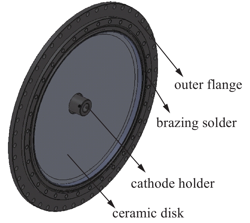
    图  2  一种同轴馈电型陶瓷真空界面

    Figure  2.  A disk type ceramic-metal interface with coaxial power supply

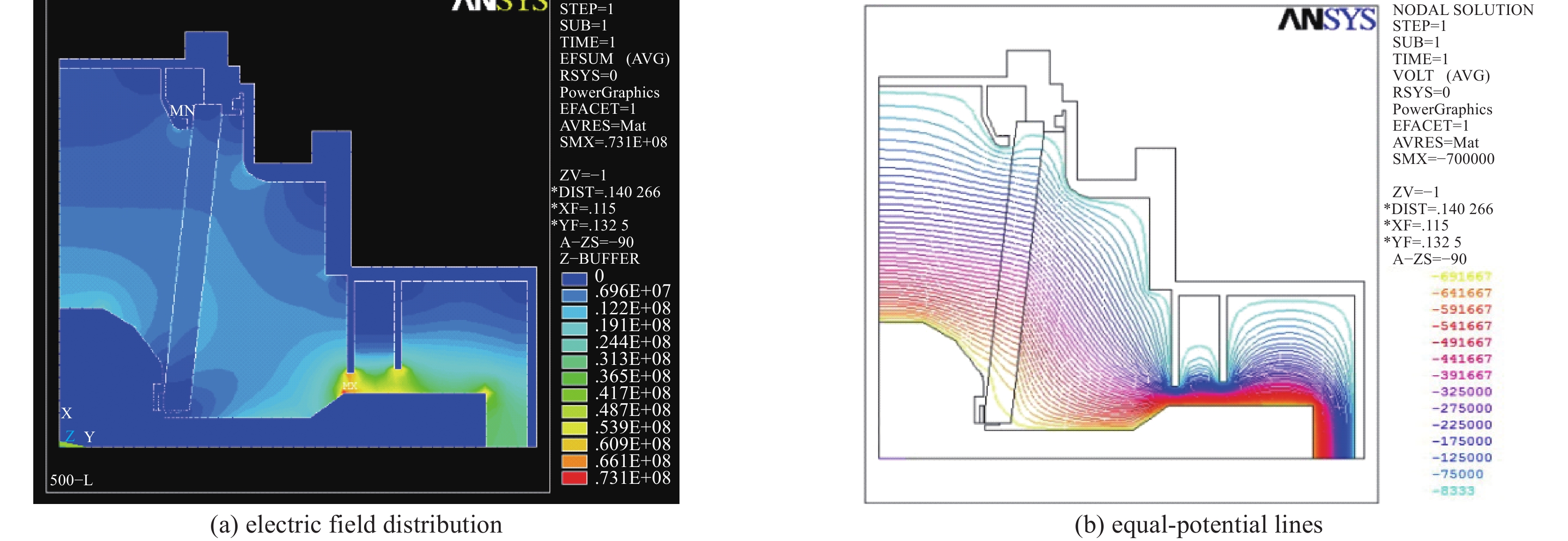
    图  3  驱动微波源负载的绝缘结构模型及静电场模拟结果

    Figure  3.  Electro-static simulation results of the insulation structure

    图  4  陶瓷真空界面典型重复频率测试结果

    Figure  4.  Typical repetitive results of the ceramic insulation structure

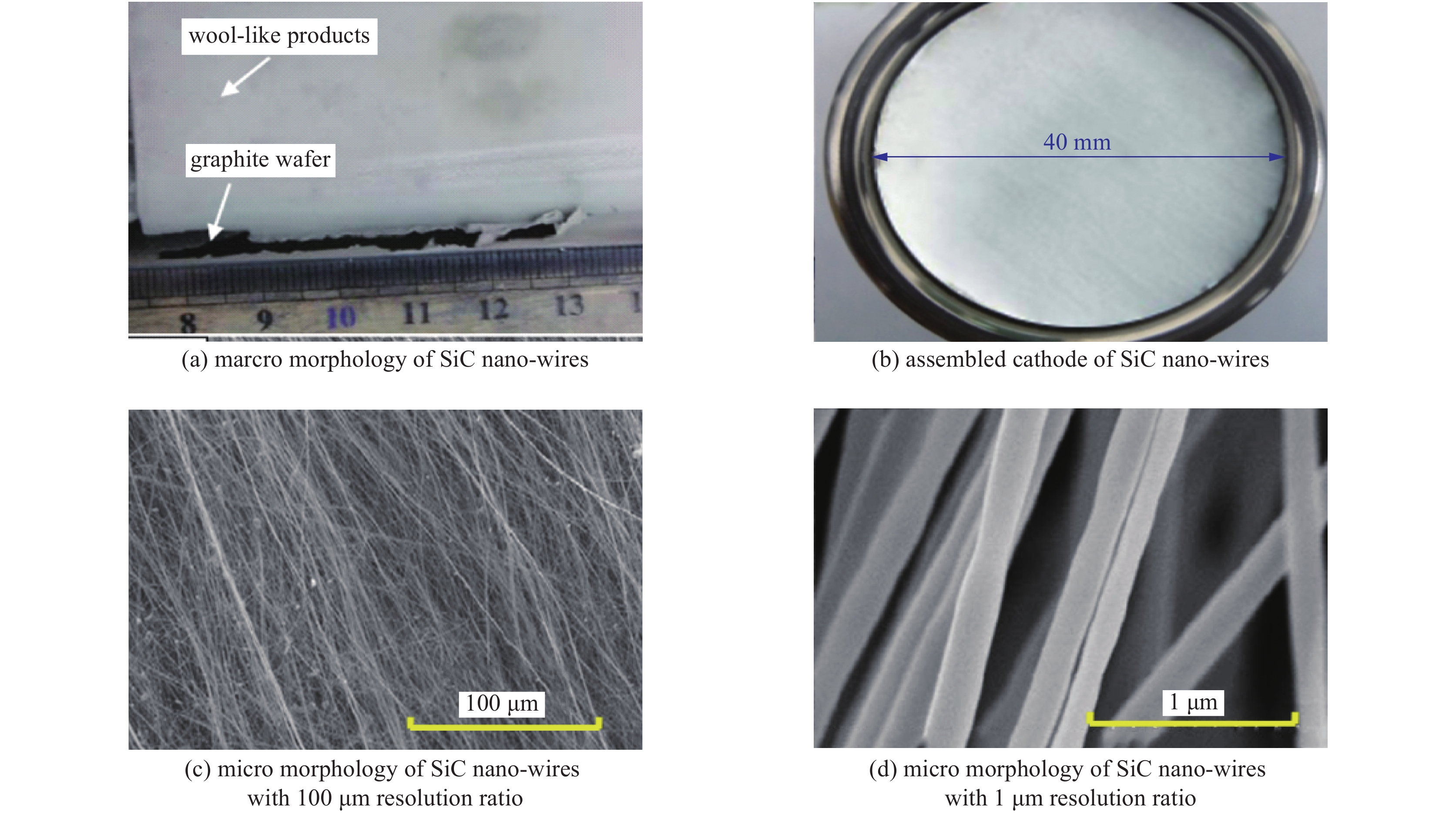
    图  5  SiC纳米线微观结构及阴极实物

    Figure  5.  Structure of SiC nano-wire

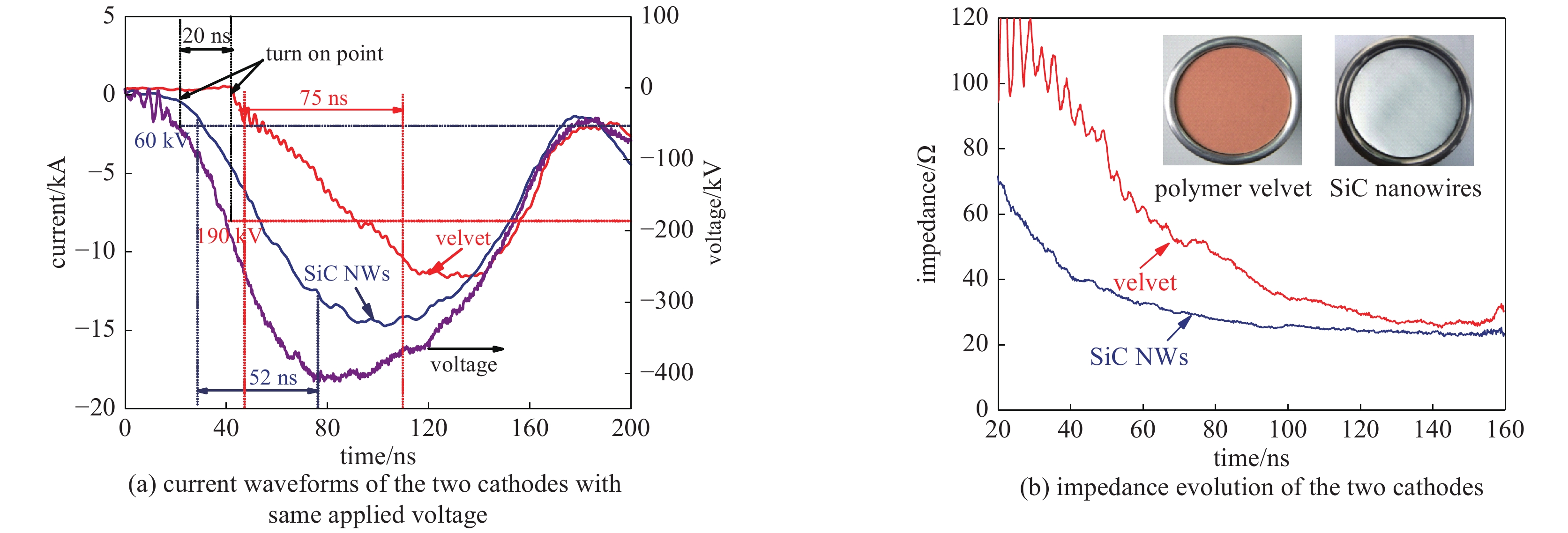
    图  6  SiC纳米线阴极与常规阴极典型比较结果

    Figure  6.  Comparision of SiC nano-wires and velvet cathodes

    图  7  两种阴极重复频率运行稳定性比较

    Figure  7.  Comparision of stability of the two cathodes under repetitive operation

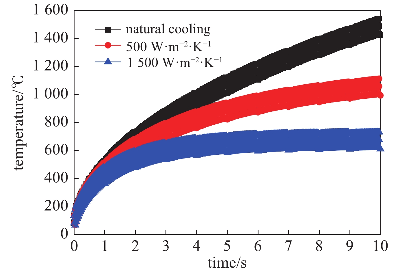
    图  8  收集极典型温度历史曲线模拟结果

    Figure  8.  Temperature evolution of the collector

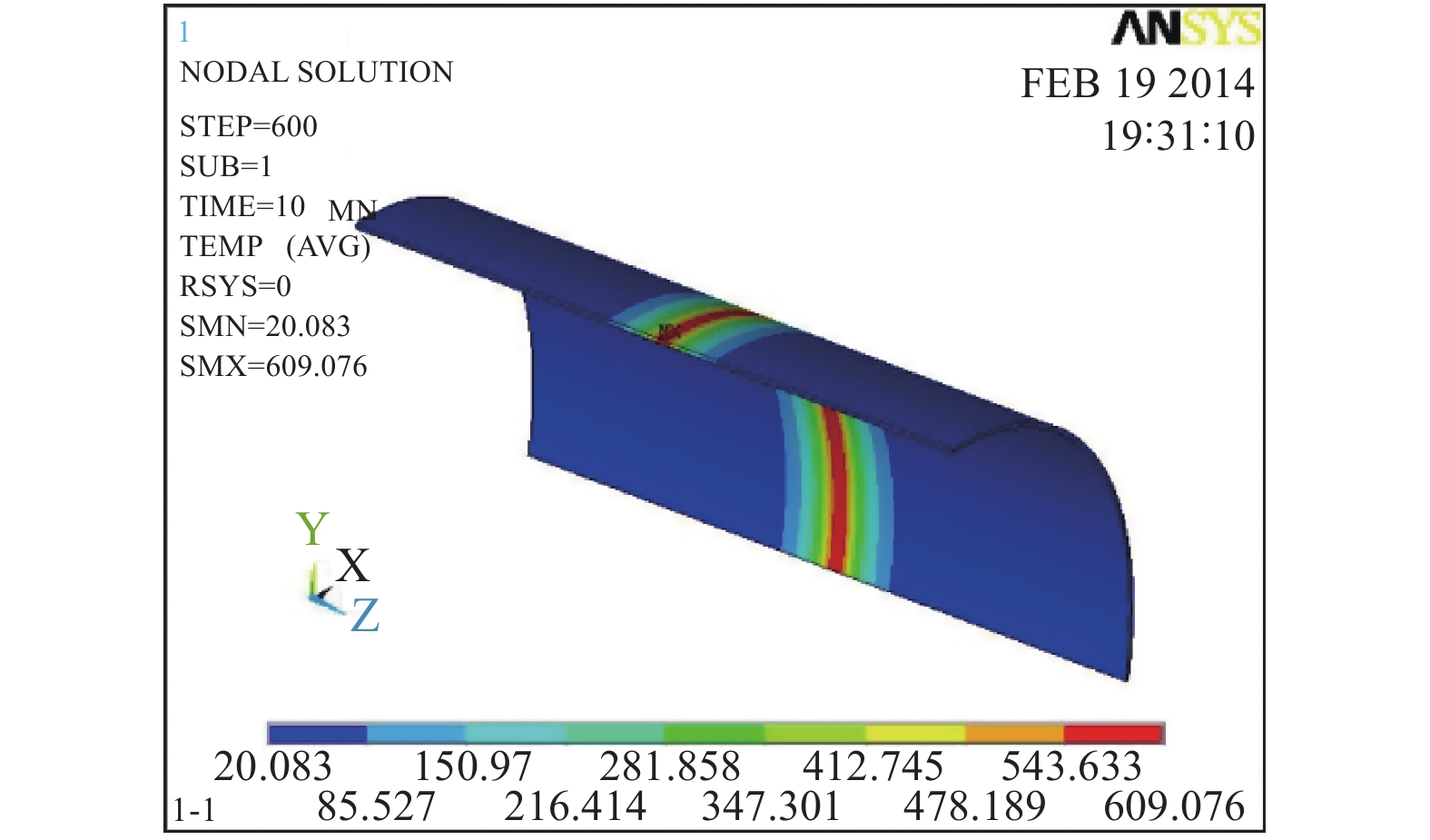
    图  9  连续运行10 s后的温度分布(hc=3000 W·m−2·K−1

    Figure  9.  Temperature distribution after 10 s continuous operation

    图  10  螺旋水道典型流体模拟结果

    Figure  10.  Typical fluid simulation results of the spiral flow channel

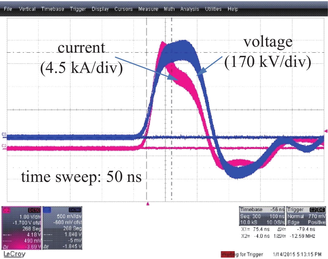
    图  11  收集极耐受长脉冲(150 ns)、30 Hz典型电压电流波形(300 个脉冲)

    Figure  11.  The applied pulsed power on the collector (150 ns, 30 Hz, and 300 pulses)

  • [1] Benford J, Swegle J A, Schamiloglu E. High power microwaes[M]. 3rd ed. London: Taylor & Francis Group, 2015.
    [2] Walter J W, Lynn C F, Dickens J C, et al. Operation of a sealed-tube-vircator high-power-microwave source[J]. IEEE Trans Plasma Science, 2012, 40(6): 1618-1621. doi: 10.1109/TPS.2012.2192454
    [3] Xun Tao, Yang Hanwu, Zhang Jiande, et. al A ceramic radial insulation structure for a relativistic electron beam vacuum diode[J]. Review of Scientific Instruments, 2008, 79: 063303. doi: 10.1063/1.2936884
    [4] Xun Tao, Zhang Jiande, Yang Hanwu, et al. A distributed pumping model for a repetitive operated magnetically insulated transmission line oscillator[J]. Journal of Applied Physics, 2013, 113: 164505. doi: 10.1063/1.4803056
    [5] Xun Tao, Fan Yuwei, Yang, Hanwu, et al. A vacuum-sealed, giga-watt class, repetitively pulsed high-power microwave source[J]. Journal of Applied Physics, 2017, 121: 234502. doi: 10.1063/1.4986632
    [6] Xun Tao, Zhang Jiande, Yang Han-Wu, et al. Hydrodynamic loading of ceramic components due to pulsed discharge in water[J]. IEEE Trans Plasma Science, 2009, 37(10): 1975-1979. doi: 10.1109/TPS.2009.2016201
    [7] Xun Tao, Yang Hanwu, Zhang Jiande. A high-vacuum high-electric-field pulsed power interface based on a ceramic insulator[J]. IEEE Trans Plasma Science, 2015, 43(12): 4130-4135. doi: 10.1109/TPS.2015.2497276
    [8] Krasik Y E, Yarmolich D, Gleizer J Z, et al. Pulsed plasma electron sources[J]. Physics of Plasmas, 2009, 16(5): 7103.
    [9] Liu Guozhi, Sun Jun, Shao Hao, et al. Research on an improved explosive emission cathode[J]. Journal of Physics D: Applied Phyics, 2009, 42(12): 5204-5209.
    [10] Zhang Jun, Jin Zhenxing, Yang Jianhua, et al. Recent advance in long-pulse HPM sources with repetitive operation in S-, C-, and X-bands[J]. IEEE Trans Plasma Science, 2011, 39(6): 1438-1445. doi: 10.1109/TPS.2011.2129536
    [11] Shiffler D, Haworth M, Cartwright K, et al. Review of cold cathode research at the Air Force Research Laboratory[J]. IEEE Trans Plasma Science, 2008, 36(3): 718-728. doi: 10.1109/TPS.2008.926227
    [12] Levine J S, Harteneck B D. Repetitively pulsed relativistic klystron amplifier[J]. Applied Physics Letter, 1994, 65: 2133-2135. doi: 10.1063/1.112813
    [13] Xun Tao, Yang Hanwu, Zhang Jiande, et al. Effects of vacuum pressures on the performance of a velvet cathode under repetitive high-current pulse discharges[J]. Vacuum, 2010, 85: 322-326. doi: 10.1016/j.vacuum.2010.07.004
    [14] Xun Tao, Zhang Jiande, Yang Hanwu, et al. Characteristics of a velvet cathode under high repetition rate pulse operation[J]. Physics of Plasmas, 2009, 16: 103106. doi: 10.1063/1.3254043
    [15] Xun Tao, Zhao Xuelong, Li Gongyi, et al. High-current, pulsed electron beam sources with SiC nanowire cathodes[J]. Vacuum, 2015, 125: 81-84.
    [16] Xun Tao, Zhang Jiande, Li Gongyi, et al. Performance of a SiC-nanowire-based explosive-emission pulsed plasma electron source[J]. Applied Physics Express, 2016, 9: 106001. doi: 10.7567/APEX.9.106001
    [17] Friedman M, Myers M C, Chan Y, et al. Properties of ceramic honeycomb cathodes[J]. Applied Physics Letter, 2008, 92: 141501. doi: 10.1063/1.2904637
    [18] Dunaevsky A, KrasikYa E, Feisteiner J, et al. Electron diode with a large area ferroelectric plasma cathode[J]. Journal of Applied Physics, 2001, 90(8): 3689-3698. doi: 10.1063/1.1402149
    [19] KrasikYa E, Gleizer J Z, Yarmolich D, et al. Characterization of the plasma on dielectric fiber (velvet) cathodes[J]. Journal of Applied Physics, 2005, 98: 093308. doi: 10.1063/1.2126788
    [20] 梁玉钦, 邵浩, 孙钧, 等. 引导磁场对收集极中电子能量沉积的影响[J]. 强激光与粒子束, 2014, 25:063010. (Liang Yuqin, Shao Hao, Sun Jun, et al. Influence of guiding magnetic field on energy deposition of electrons in collector[J]. High Power Laser and Particle Beams, 2014, 25: 063010
    [21] 荀涛, 杨汉武, 张自成, 等. 重复频率运行强流电子束收集极热特性[J]. 强激光与粒子束, 2011, 22(11):3064-3068. (Xun Tao, Yang Hanwu, Zhang Zicheng, et al. Thermal characteristics of repetitively operated high-current beam collector[J]. High Power Laser and Particle Beams, 2011, 22(11): 3064-3068
    [22] 霍少飞, 孙钧, 梁玉钦, 等. 不锈钢电子束收集极的损伤能量密度阈值[J]. 强激光与粒子束, 2014, 26:063008. (Huo Shaofei, Sun Jun, Liang Yuqin, et al. Damage threshold of energy density of stainless steel electron beam collector[J]. High Power Laser and Particle Beams, 2014, 26: 063008
    [23] Ju Jinchuan, Fan Yuwei, Zhong Huihuang, et al. An improved X-band magnetically insulated transmission line oscillator[J]. Physics of Plasmas, 2009, 16: 073103. doi: 10.1063/1.3160625
    [24] Cai Dan, Liu Lie, Ju Jinchuan, et al. Simulative research on the anode plasma dynamics in the high-power electron beam diode[J]. Physics of Plasmas, 2015, 22: 073108. doi: 10.1063/1.4926580
    [25] Mesyats G A. Cathode phenomena in a vacuum discharge: The breakdown, the spark and the Arc[M]. Moscow: Nauka, 2000.
    [26] Xun Tao, Yang Hanwu, Zhang Jun, et al. Properties of an intensive relativistic electron beam collector under repetitive pulse operation[J]. IEEE Trans Plasma Science, 2016, 44(6): 957-962. doi: 10.1109/TPS.2016.2556942
    [27] Li GongYi, Li Xiaodong, Chen Zhongdao, et al. Large areas of centimeters-long SiC nanowires synthesized by pyrolysis of a polymer precursor by a CVD route[J]. Journal of Physics and Chemistry C, 2009, 113: 17655-17660. doi: 10.1021/jp904277f
    [28] Shultis J K, Faw R E. Fundamentals of nuclear science and engineering[M]. New York: Dekker, 2002.
  • 期刊类型引用(1)

    1. 刘欢, 唐曌堃. 基于计算机视觉的易碎产品包装检测系统设计. 自动化与仪器仪表. 2019(12): 30-33 . 百度学术

    其他类型引用(0)

  • 加载中
图(11)
计量
  • 文章访问数:  1561
  • HTML全文浏览量:  772
  • PDF下载量:  183
  • 被引次数: 1
出版历程
  • 收稿日期:  2019-09-23
  • 修回日期:  2019-12-03
  • 刊出日期:  2019-12-26

目录

/

返回文章
返回