Basic types and technological implementation of charged particle accelerators
-
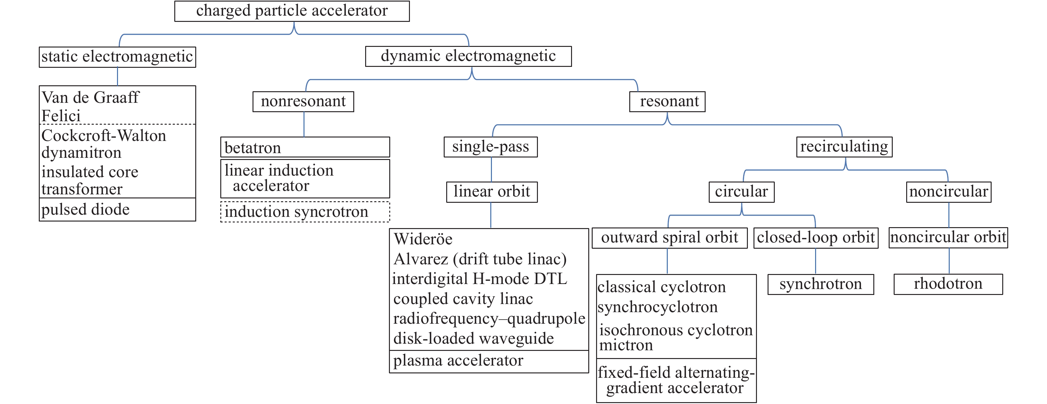
摘要: 现代粒子加速器的发展已有100年的历史。给出了粒子加速器主要类型的简单分类图表,从粒子加速器发展过程中相关概念演变和加速器技术逻辑发展的角度,概述了粒子加速器的基本类型、基本工作原理、相应的技术实现途径以及各类加速器的典型的技术特征。Abstract: The modern particle accelerators have developed greatly over the last 100 years. This article provides an overview of all main types of particle accelerators. Simple charts are given to exhibit conceptual and technological evolutions of major particle accelerators. It also briefly introduces the basic types, fundamental principles, technological approaches, and typical technical features of various types of particle accelerators.
-
Since the old 200 kW tetrode amplifier had been operating in high current beam of a Radio Frequency Quadrupole (RFQ) cavity without a circulator for more than two years, two new solid-state amplifiers (SSAs), which can operate under the full mismatch condition for a time period as long as several hours, were considered to replace it on site due to their specialties of anti-reflection. SSA is very attractive for individually driven independently phased cavities in proton linear accelerators, because it has such features of MOSFETs like linearity, low noise, high efficiency, high reliability, low cost and long lifetime.
RFQ cavity operates at 162.5 MHz, the dissipated power reaches up to approximately 90 kW, and especially, the beam power was 21 kW while 10 mA beam current was applied[1]. In Beijing Broadcast Equipment Factory (BBEF) design of amplifier, we found the solution of a distributed protection cheaper than the one with a big circulator and an RF termination at the amplifier output. Thus, a power circulator and an RF termination are included inside every module to protect the MOSFET against excess reflected power. Furthermore, some special technologies of new generation SSA were developed for this kind of high intensity accelerator, such as two types of reflection power experiments on module including long-term continuous wave power and four times pulsed power within 20 ms. Due to the very high power, the design of power module and combiner need to optimize the scattering parameters in the case of mismatch resulting from the multi-port balance or cavity sparking.
In addition, Low Level RF system (LLRF) must adjust the offsets of output gain and phase due to the different output characteristics from two amplifiers of different manufacturers, BBEF Science & Technology Co. Ltd and Chengdu Kaiteng Sifang Digital Radio & TV Equipment Co. Ltd. The operating mode of this kind of RF system, whose RF power on two identical couplers comes from different amplifiers, implies the balance output power gain and phase be considered at the same time, so that the attenuator and phase shifter were adjusted carefully for the nominal power output and linear region amplification[2].
1. Solid-state amplifier modules failure
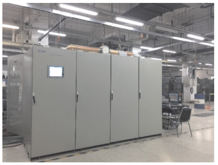
In order to sum the power coming from over 120 modules, several level synthesizers are used for full power output, which is shown in Fig. 1, and every module can provide a maximum of 850 W RF power for the nominal power even when one pre-amplifier fails. Thus, the tuning process of amplitude and phase from the modules was very complicated due to too many modules. All the modules have been individually tested before combining them. Several tests were carried out by using a network analyzer to determine the S-parameters at low power as well as a power meter, an oscilloscope and a spectrum analyzer to measure characteristics at high power. In the latter case the monitoring devices were connected either to a directional coupler between the module and the load or to a high-power attenuator.
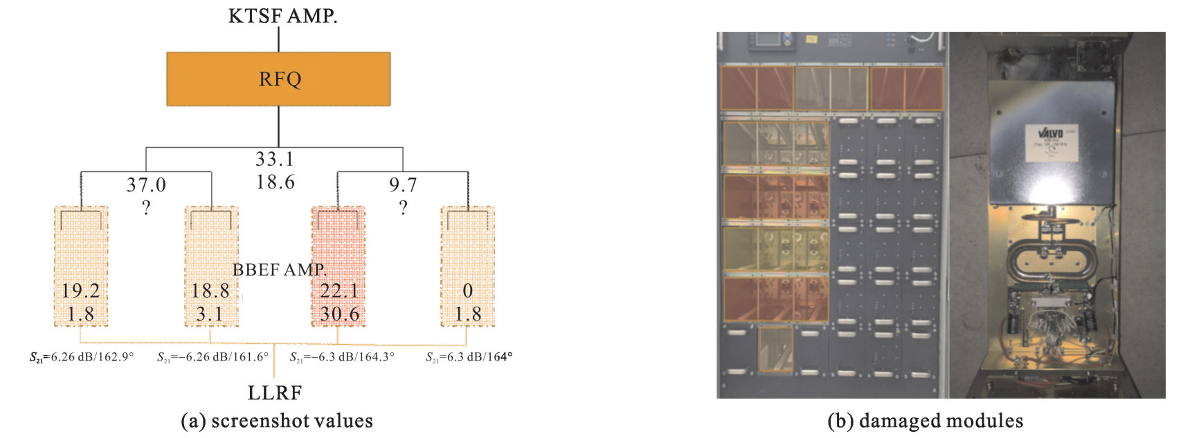
At a serious accident of June 2017, 19 power modules were burned simultaneously. Almost all power transistors, circulators and sink loads (connected directly with the circulators) in these modules were damaged seriously and must be replaced. When failure happened, the power values were recorded from the monitoring system shown in the screen of a control system, as were presented in Fig. 2 (a). Fig. 2 (b) is a photo of the damaged modules.
During the operation, the two SSAs were both consisted of four 19″(48.26 cm) racks to integrate gradually, each rack could provide 50 or 60 kW RF power (without beam or with 10 mA CW beam) for separate coupler at the same time. Before basic analysis and check on the machine, one possible reason of accident should be the highly sensitive driving signal interlock in the third section compared to the other three racks, the input signal of the third section was shut down suddenly because of abnormal interlock during the operation, the other three sections were influenced to increase power rapidly at that time due to LLRF close loop on the amplitude modulation. Furthermore, the weird (all at left side of the third section) location of all damaged modules indicates that some inappropriate RF configuration needs to be modified and optimized.
2. Analysis from simulation
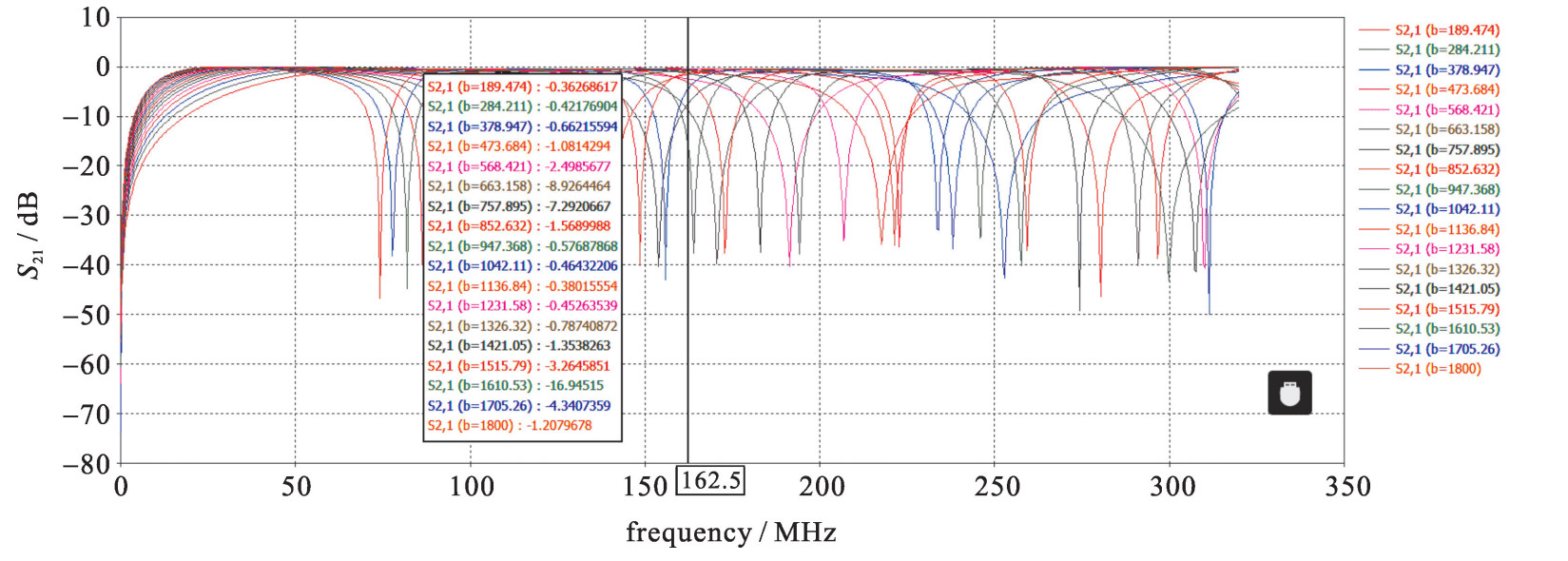
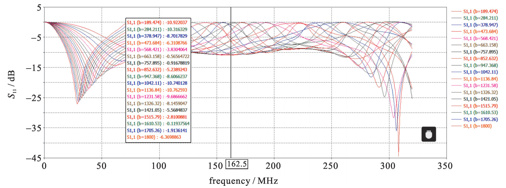
For the convenience of analysis, a corresponding model of a multi-port power combiner was created in simulation software Microwave Studio to figure out the variation regularities of the scattering parameter. According to the simulated results, if any one port was open or short, the parameter S21 along transmission line on the port had a very great fluctuation along the whole phase range, even when the wavelength moved to a certain value, the scattering parameter would take dramatic turn to block the RF signal. Fig. 3 shows the sweep results in CST simulation, which indicates there are some reflected power points to block the power through combiners when one or a couple of ports fail.
Generally, one advantage of SSA is continuing output while one or some modules fail, however, the output power decreases. For instance, n modules fail in a 6 kW combiner with 8 modules, the output power is degraded (8-n)2/82×100%. The situation would be much complicated while the circulators inside the module were broken rather than the field-effect transistors. The analysis of n ports network is gained through the degraded matrix[3], Sm=SⅡ+SⅡГ(I-SⅣ)-1SⅢ [4] (the roman letter subscripts represent different sections, n ports connect to arbitrary loads, in which m ports deal with no load, i.e., full reflection). According to symmetry and lossless combination of nine ports device, the matrix of a 8-1 combiner is
S=[−7818⋯18√1818⋱⋯18⋮⋮⋮⋱18⋮181818−78√18√18⋯⋯√180](9∗9) (1) thus its degraded matrix while mismatch (full reflection) is
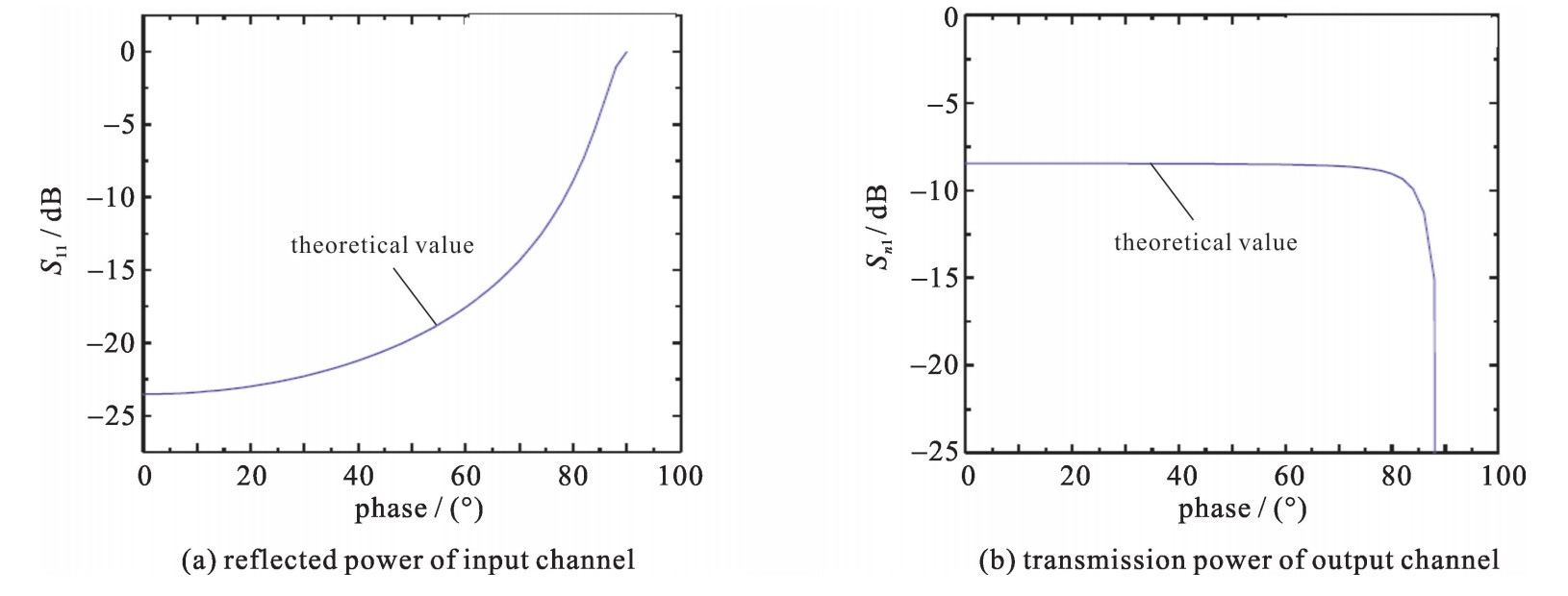
S=[164e2φi+56−78164e2φi+56+78⋯164e2φi+56+78√232e2φi+28+√24164e2φi+56+78⋱⋯⋮⋮⋮⋮⋱⋮⋮164e2φi+56+78⋯⋯⋱√232e2φi+28+√24√232e2φi+28+√24⋯⋯√232e2φi+28+√2418e2φi+7](8∗8) (2) When one output port was short, the degenerate matrix[5] can be deduced Eq.(2). So, when the phase of short port was 0 or π, the minimum S11 (S11 is reflection of the first port, while Sn1 represents transmission of the nth port) of 0.066 7 and reflected power of input port would be gained simultaneously; when the phase was 90°, S11 got the maximum value of -1 to mean the full power reflection[6]. The S11 and Sn1 were plotted in Fig. 4 according to the matrix of Eq.(2).
3. Experiments focused on simulation
Obviously, the results from Eq.(2) had a good agreement with the CST simulated ones. Then a targeted experiment was prepared for this situation, which took advantage of a three-level combiner/ divider to measure the scattering parameter while any one port mismatched (short or open circuit). An 8-way combiner/ divider was designed and manufactured into a three-level circuit for the purpose of changing the wavelength between the different levels in Fig. 5.
For these three-level combiners[7], the failure of one port would lead to change greatly, even block RF signal completely. According to the rule of scattering parameter, S11 along the transmission line of full reflection point will fluctuate severely, as Fig. 6 shows.
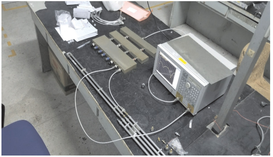
The measured results indicate the simula-tion with one port failure right in this three-stage combiner workbench shown in Fig. 7, the VNA (Vector Network Analyzer) could gain precisely scattering parameters and phase when one port was connected with the phase shifter and the open/short terminator.
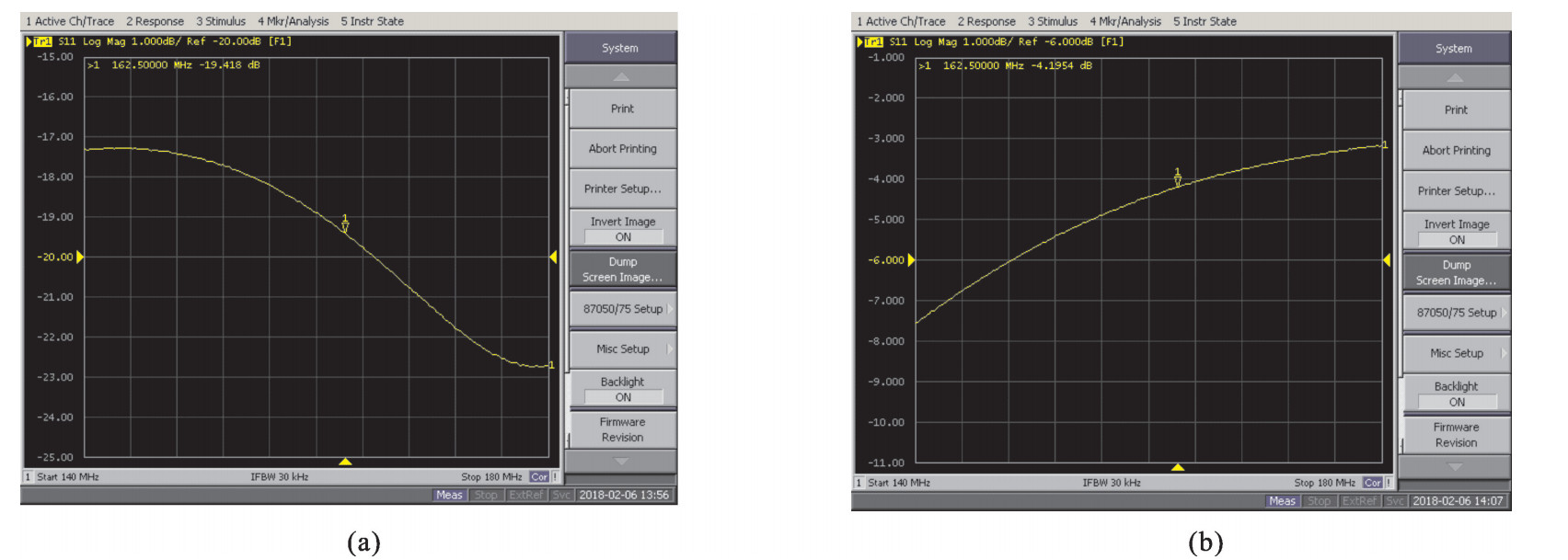
The S parameters were measured using the workbench (Fig. 7). When only one port mismatched, the S11 excessing -20 dB indicates a very good matching (Fig. 8(a)). And in Fig. 8(b), the maximum S11 would reach up to -5 dB, which means serious mismatching when one port fails. As a result, the scattering parameter was analyzed to find out the specific regularities while the phase of the phase shifter changed gradually.
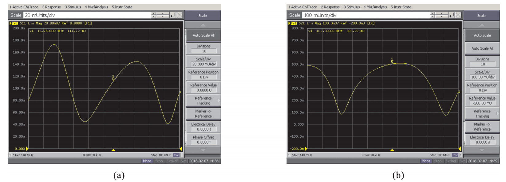
According to the measurements, the electrical length of one phase shifter was about 118° at 162.5 MHz. Three phase shifters can cover the whole range of the S parameter, the worst matching (the block point) is shown in Fig. 9.
4. Conclusion
From the previous simulations and related experiments, it is obvious which of the power modules with circulator was damaged or burned down due to the severe power reflection, one reason was the unreasonable electrical length configuration between the two different levels of combiners when it is uncertain one or several ports mismatch during the operation. While the phase value meets the particular demand, the power transmission may attenuate extremely on modules, even block power completely. Thus, the very high reflected power from cavity or ports balance mismatching have a risk to accumulate on power module.
The measurement on 8-way combiners obtained an optimum compliance to the simulation requirements. Now, five new SSAs are designed and calculated in BBEF, according to the previous experiences, the devices have shown very good characteristics of efficiency, stability, harmonics and cost, with tolerable operating risk (high risk will come from combining a large number of units). Extended versions of the module with an output power from 850 W up to 1000 W are certainly feasible on the basis of the described design concept. The next step of the development program is to study the phase relationship while any one port fails for improving reliability and reduce the risk of failure.
-
图 24 花瓣形加速器加速结构示意图[58]
Figure 24. Rhodotron acceleration scheme
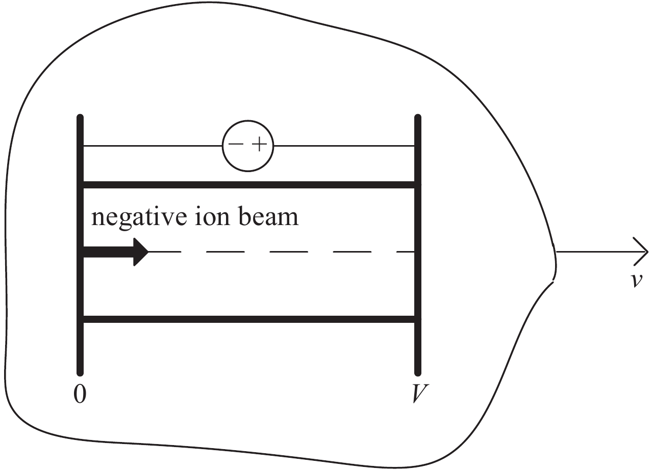
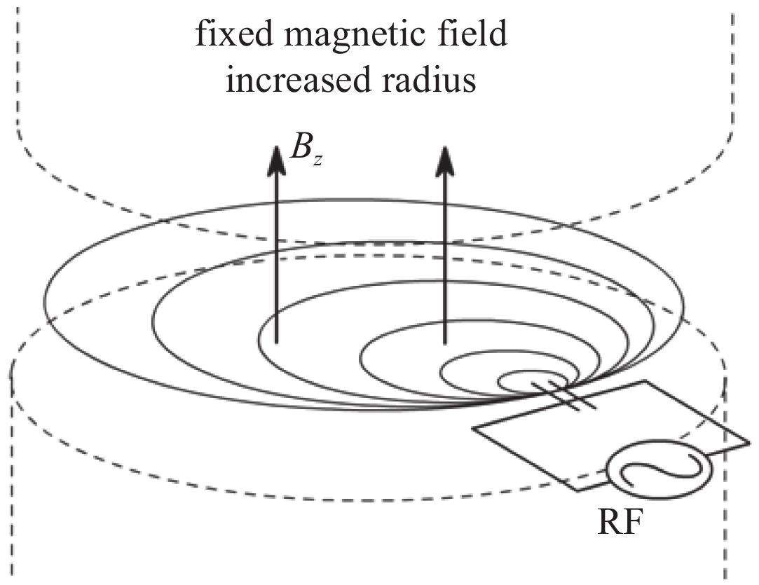
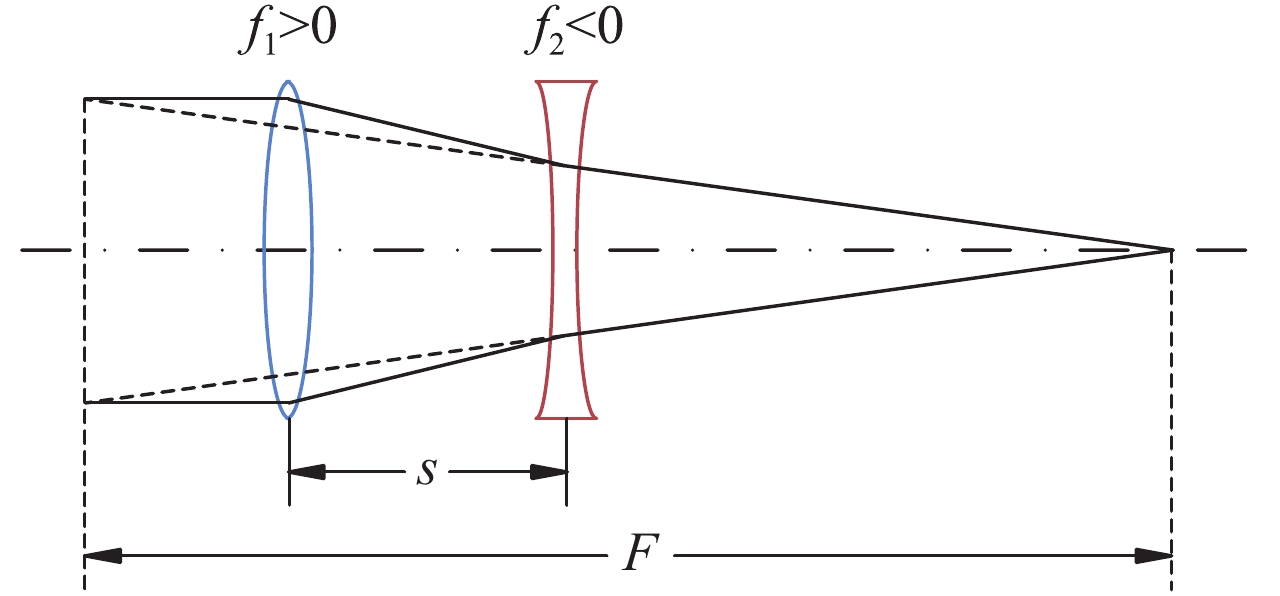
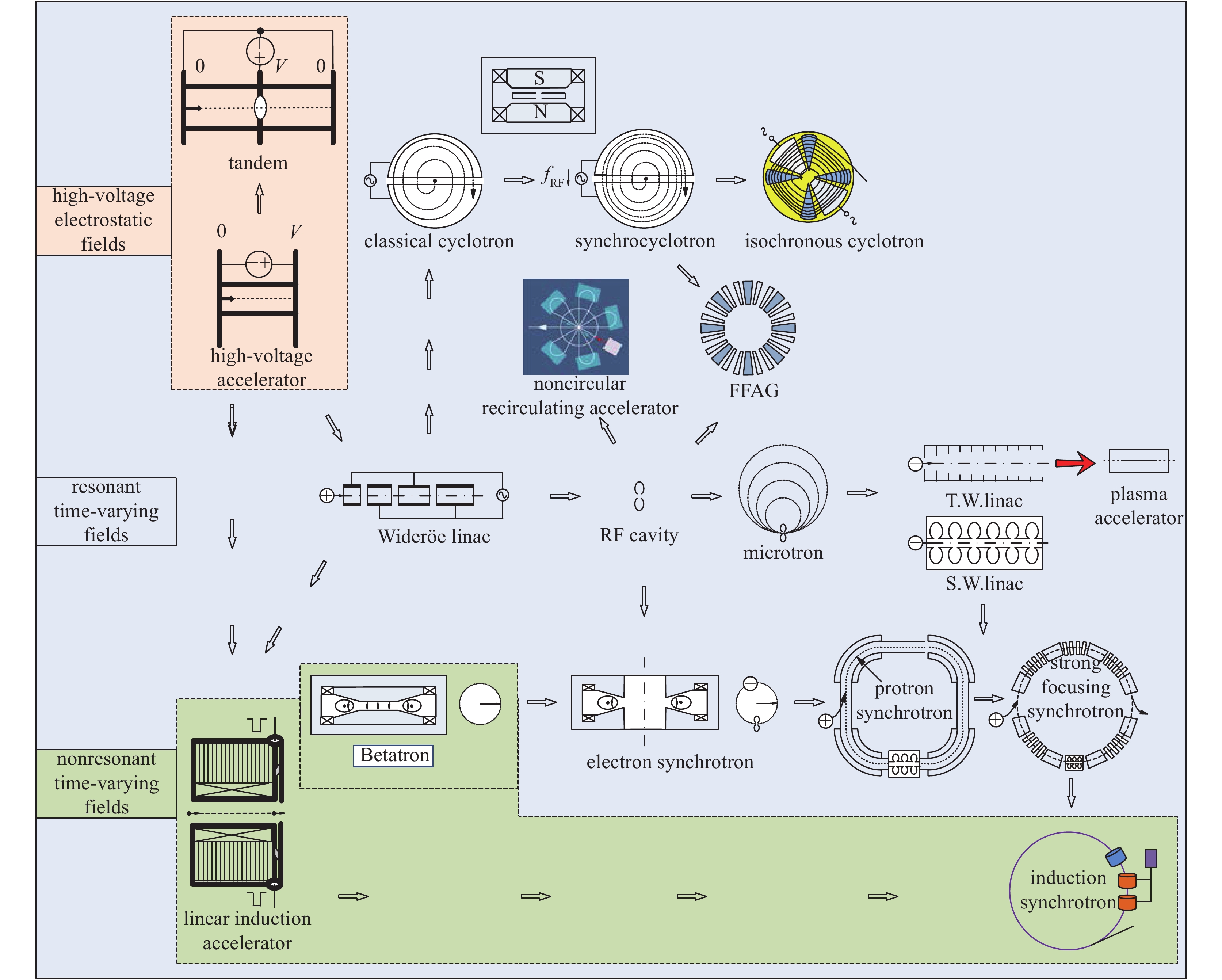
图 25 各类典型加速器的相互联系示意图
Figure 25. Evolution of acceleration mechanism(modified from Ref.[3])
-
[1] 方守贤, 梁岫如. 神通广大的射线装置: 带电粒子加速器[M]. 北京: 清华大学出版社, 2001.Fang Shouxian, Liang Xiuru. Infinitely resourceful ray facilities: charged particle accelerators[M]. Beijing: Tsinghua University Press, 2001 [2] 陈佳洱. 加速器物理基础[M]. 北京: 北京大学出版社, 2012.Chen Jiaer. An introduction to the physics of particle accelerators[M]. Beijing: Beijing University Press, 2012 [3] 桂伟燮. 荷电粒子加速器原理[M]. 北京: 清华大学出版社, 1994.Gui Weixie. Principles of charged particle accelerator[M]. Beijing: Tsinghua University Press, 1994 [4] 谢家麟. 加速器与科技创新[M]. 北京: 清华大学出版社, 2000.Xie Jialin. Accelerators and technological innovations[M]. Beijing: Tsinghua University Press, 2000 [5] Wiedemann H. Particle accelerator physics[M]. New York: Springer International Publishing, 2015. [6] Teng L C. Conceptual and technological evolutions of particle accelerators[J]. High Energy Physics and Nuclear Physics, 2009, 33(s2): 112-114. [7] Sessle A, Wilson E. Engines of discovery, a century of particle accelerators[M]. Singapore : World Scientific Publishing Co Pte Ltd, 2014. [8] Chao A W, Tigner M. Handbook of accelerator physics and engineering[M]. Singapore : World Scientific Publishing Co Pte Ltd, 2006. [9] Humphries S. Principles of charged particle acceleration[M]. New York: Wiley, 1999. [10] Takayama K, Briggs R J. Induction accelerators[M]. New York: Springer International Publishing, 2011. [11] Edwards D A, Syphers M J. An introduction to the physics of high energy accelerators[M]. Weinheim: Wiley-VCH Verlag GmbH&Co KGaA, 2004. [12] Chakhlov S V, Kasyanov S V, Kasyanov V A, et al. Betatron application in mobile and relocatable inspection systems for freight transport control[J]. Journal of Physics: Conference Series, 2016, 671: 012024. doi: 10.1088/1742-6596/671/1/012024 [13] 刘锡三. 强流粒子束及其应用[M]. 北京: 国防工业出版社, 2007.Liu Xisan. Intense particle beams and its applications[M]. Beijing: National Defense Industry Press, 2007 [14] Boucher S, Agustsson R, Frigola P, et al. High average current betatrons for industrial and security applications[C]//Proceedings of PAC. 2007. [15] Wilson P B. Electron linacs for high energy physics[J]. Reviews of Accelerator Science and Technology, 2008, 1: 7-41. doi: 10.1142/S1793626808000034 [16] 邓建军. 直线感应电子加速器[M]. 北京: 国防工业出版社, 2006.Deng Jianjun. Linear induction accelerator for electrons[M]. Beijing: National Defense Industry Press, 2006 [17] Vintizenko I. Linear induction accelerators for high-power microwave devices[M]. Boca Raton: CRC Press, 2018. [18] Zhang C, Fang S X. Particle accelerators in China[J]. Reviews of Accelerator Science and Technology, 2017, 9: 265-312. [19] Crawford M, Barraza J. Scorpius: The development of a new multi-pulse radiographic system[C]//IEEE 21st International Conference on Pulsed Power. 2017. [20] Akimov A, Akhmetov A, Bak P, et al. Single-triple pulse power supply for 2 kA, 20 MeV linear induction accelerator[C]//IEEE 21st International Conference on Pulsed Power. 2017. [21] Vermare C. Investigations on dual-pulse technologies for future upgrade of CEA flash X-rays LIA[C]//IEEE 21st International Conference on Pulsed Power. 2017. [22] 黄子平, 吕璐, 陈思富, 等. 脉冲感应加速在环形加速器中的应用[J]. 强激光与粒子束, 2017, 29:020201. (Huang Ziping, Lü Lu, Chen Sifu, et al. Application of pulse induction module in circular accelerators[J]. High Power Laser and Particle Beams, 2017, 29: 020201 doi: 10.11884/HPLPB201729.160460 [23] 徐玉存. MOSFET调制器关键技术及氦离子FFAG感应加速腔模拟研究[D]. 合肥: 中国科学技术大学, 2011.Xu Yucun. Study of the MOSFET modulator and conceptual design of an induction cavity for the He2+ FFAG accelerator[D]. Hefei: University of Science and Technology of China, 2011 [24] Smith I D. Induction voltage adders and the induction accelerator family[J]. Phys Rev ST Accel Beams, 2004, 7: 064801. doi: 10.1103/PhysRevSTAB.7.064801 [25] Melissinos A C. Nicholas C Christofilos: His contributions to physics[C]//CERN Accelerator School Fifth Advanced Accelerator Physics Course. 1995, 2: 1067-1081. [26] 周良骥. 快脉冲直线变压器驱动源(LTD)技术初步研究[D]. 绵阳: 中国工程物理研究院, 2006.Zhou Liangji. Research of linear transformer driver (LTD)[D]. Mianyang: China Academy of Engineering Physics, 2006 [27] 盛政明, 张杰. 由激光在等离子体中激发的尾波场产生的超强太赫兹电磁辐射[J]. 激光与光电子学进展, 2005, 42(12):35-36. (Sheng Zhengming, Zhang Jie. Super electromagnetic radiation produced by a laser-plasma wakefield[J]. Laser & Optoelectronics Progress, 2005, 42(12): 35-36 [28] Amaldi U. Particle accelerators: from big bang physics to hadron therapy[M]. New York:Springer International Publishing, 2015. [29] Tang Chuanxiang. Low energy accelerators for cargo inspection[J]. Reviews of Accelerator Science and Technology, 2015, 8: 143-163. doi: 10.1142/S179362681530008X [30] 刘渭滨. 高能(射频)直线加速器物理[R]. 北京: 中国科学院高能物理研究所加速器中心, 2011.Liu Weibin. Radio frequency linear accelerator physics[R]. Beijing: Institute of High Energy Physics Accelerator Center, 2011 [31] Wangler T P. RF linear accelerator[M]. Weinheim: Wiley-VCH Verlag GmbH&Co KGaA, 2008. [32] 杜衡. IH-DTL直线加速器的设计及实验研究[D]. 兰州: 中国科学院近代物理研究所, 2017.Du Heng. Design and experiment study of IH-DTL linac[D]. Lanzhou: Institute of Modern Physics, Chinese Academy of Sciences, 2017 [33] 刘乃泉. 加速器理论[M]. 北京: 清华大学出版社, 2004.Liu Naiquan. Theory of particle accelerator[M]. Beijing: Tsinghua University Press, 2004 [34] 王国林. 基于高梯度加速结构高功率测试平台控制和测量的研究[D]. 上海: 中国科学院上海应用物理研究所, 2015.Wang Guolin. The research of control and measurement of the high power testing platform based on high-gradient accelerating structures[D]. Shanghai: Shanghai Institute of Applied Physics, Chinese Academy of Sciences, 2015 [35] 黄晓霞. X 波段高梯度加速结构及尾场效应研究[D]. 上海: 中国科学院上海应用物理研究所, 2017.Huang Xiaoxia. Study of the X-band high gradient accelerating structure and wakefield effects[D]. Shanghai: Shanghai Institute of Applied Physics, Chinese Academy of Sciences, 2017 [36] 邵佳航. 高梯度加速结构中射频击穿现象的研究[D]. 北京: 清华大学, 2016.Shao Jiahang. Investigations on rf breakdown phenomenon in high gradient accelerating structures[D]. Beijing: Tsinghua University, 2016 [37] Ioshi C. The development of laser- and beam-driven plasma accelerators as an experimental field[J]. Phys Plasmas, 2007, 14: 055501. doi: 10.1063/1.2721965 [38] Hogan M J. Electron and positron beam-driven plasma acceleration[J]. Reviews of Accelerator Science and Technology, 2016, 9: 63-83. doi: 10.1142/S1793626816300036 [39] Adli E, Muggli P. Proton-beam-driven plasma acceleration[J]. Reviews of Accelerator Science and Technology, 2016, 9: 85-104. doi: 10.1142/S1793626816300048 [40] 盛政明, 陈民, 翁苏明, 等. 超短超强激光驱动新型粒子加速器: 机遇和挑战[J]. 物理, 2018, 47(12):753-762. (Sheng Zhenming, Chen Min, Weng Suming, et al. Novel particle accelerators driven by ultrashort and ultraintense lasers: opportunities and challenges[J]. Phyisics, 2018, 47(12): 753-762 doi: 10.7693/wl20181201 [41] 胡荣豪, 颜学庆. 激光等离子体加速器: 原理、现状以及展望[J]. 现代物理知识, 2017(5):35-39. (Hu Ronghao, Yan Xueqing. Laser-driven plasma accelerators: principles, status and expectations[J]. Modern Physics, 2017(5): 35-39 [42] Bolton P R, Parodi K, Schreiber J. Applications of laser-driven particle acceleration[M]. Boca Raton: CRC Press, 2018. [43] 高著秀, 黄建国, 韩建伟, 等. 等离子体加速器动力学理论探索[J]. 航天器环境工程, 2010, 27(3):285-289. (Gao Zhuxiu, Huang Jianguo, Han Jianwei, et al. Dynamics of plasma driven micro-particle accelerator[J]. Spacecraft Environment Engineering, 2010, 27(3): 285-289 doi: 10.3969/j.issn.1673-1379.2010.03.003 [44] Pepitone K, Doebert S, Apsimon R. The electron accelerators for the AWAKE experiment at CERN—baseline and future developments[J]. Nuclear Inst and Methods in Physics Research A, 2018, 909: 102-106. doi: 10.1016/j.nima.2018.02.044 [45] Greene K.. World record for compact particle accelerator[R]. Lawrence Berkeley National Laboratory, 2014. [46] Gonsalves A J, Nakamura K, Daniels J, et al. Petawatt laser guiding and electron beam acceleration to 8 GeV in a laser-heated capillary discharge waveguide[J]. Phys Rev Lett, 2019, 122: 084801. doi: 10.1103/PhysRevLett.122.084801 [47] Zhu Jungao, Zhu Kun, Tao Li, et al. Distribution uniformity of laser-accelerated proton beams[J]. Chinese Physics C, 2017, 41: 097001. doi: 10.1088/1674-1137/41/9/097001 [48] Wenz J, Dopp A, Khrennikov K, et al. Dual-energy electron beams from a compact laser-driven acceleration[J]. Nature Photonics, 2019, 13: 263-269. doi: 10.1038/s41566-019-0356-z [49] Smirnov V, Vorozhtsov S. Modern compact accelerators of cyclotron type for medical applications[J]. Physics of Particles and Nuclei, 2016, 47(5): 863-883. doi: 10.1134/S1063779616050051 [50] Pearson E, Kleeven W, Nuttens V, et al. Development of cyclotrons for proton and particle therapy[M]//Particle Radiotherapy: Emerging Technology for Treatment of Cancer. New Delhi: Springer India Ltd, 2016:21-36. [51] 唐靖宇, 魏宝文. 回旋加速器理论设计[M]. 合肥: 中国科技大学出版社, 2008.Tang Jinyu, Wei Baowen. Theory and design of cyclotrons[M]. Hefei: Press of University of Science and Technology of China, 2008 [52] 张天爵, 吕银龙, 王川, 等. 中国原子能科学研究院回旋加速器创新与发展60年[J]. 原子能科学技术, 2019, 53(10):2023-2030. (Zhang Tianjue, Lü Yinlong, Wang Chuan, et al. 60 years of innovation and development for cyclotron at CIAE[J]. Atomic Energy Science and Technology, 2019, 53(10): 2023-2030 [53] Craddock M K, Symon K R. Cyclotrons and fixed-field alternating-gradient accelerators[J]. Reviews of Accelerator Science and Technology, 2008, 1(1): 65-97. doi: 10.1142/S1793626808000058 [54] Ruggiero A G. Brief history of the FFAG accelerator[R]. BNL-75635-2006-CP, 2006. [55] 罗焕丽. 驱动离子束FFAG加速器与C-ADS输运中若干物理问题的探索研究[D]. 合肥: 中国科学技术大学, 2013.Luo Huanli. Research on several problems in heavy ion FFAG accelerator and C-ADS particle transporting[D]. Hefei: University of Science and Technology of China, 2013 [56] Sheehy S L. Fixed-field alternating-gradient accelerators[R]. CERN Yellow Reports, 2017. [57] Dubinov A E, Ochkina E I. Recirculating electron accelerators with noncircular electron orbits as radiation sources for applications[J]. Physics of Particles and Nuclei, 2018, 49(3): 431-456. doi: 10.1134/S1063779618030048 [58] 陈勇, 黄文会, 唐传祥. Rhodotron型加速器粒子动力学研究[J]. 高能物理与核物理, 2005, 29(2):180-185. (Chen Yong, Huang Wenhui, Tang Chuanxiang. Dynamics study of the Rhodotron accelerator[J]. High Energy Physics and Nuclear Physics, 2005, 29(2): 180-185 doi: 10.3321/j.issn:0254-3052.2005.02.014 [59] 陈勇. Rhodotron型加速器的动力学研究[D]. 北京: 清华大学, 2005.Chen Yong. Dynamics study of the Rhodotron accelerator[D]. Beijing: Tsinghua University, 2005 [60] 赵籍九, 尹兆升. 粒子加速器技术[M]. 北京: 高等教育出版社, 2006.Zhao Jijiu, Yin Zhaosheng. Particle accelerator technology[M]. Beijing: Higher Education Press, 2006 期刊类型引用(9)
1. 杨铭杰,杨鸿飞,张明,瞿波. 低抖动激光触发伪火花开关的研究. 强激光与粒子束. 2024(03): 146-151 .  本站查看
本站查看2. 樊琪,臧航,郭旗,燕宏斌,史成城,上官靖斌,张云. 基于PREF的扫描磁铁电源设计与实现. 强激光与粒子束. 2024(03): 110-115 .  本站查看
本站查看3. 乔笑斐,路昊明. 粒子物理学的当代转向 浅析中国大型对撞机争论之历史背景与时代困境. 科学文化评论. 2022(01): 16-32 .  百度学术
百度学术4. 魏浩,孙凤举,邱爱慈,杨海亮,尹佳辉,张鹏飞,姜晓峰,王志国. 国际高能脉冲X射线闪光照相加速器的发展综述. 强激光与粒子束. 2022(09): 19-28 .  本站查看
本站查看5. 乔笑斐,路昊明. 苏联和美国在粒子物理领域的交流、合作与竞争. 自然辩证法通讯. 2022(10): 56-64 .  百度学术
百度学术6. 李元,温嘉烨,李林波,郜晶,石亚轩,刘志濠,张冠军. 液体介质微/纳秒脉冲放电的特性与机理:现状及进展. 强激光与粒子束. 2021(06): 6-18 .  本站查看
本站查看7. 殷佳鹏,远晓辉,周祖圣,裴国玺,刘圣广. 新型金属丝靶电子源实验研究(英文). 强激光与粒子束. 2021(09): 117-122 .  本站查看
本站查看8. 乔舰,谢修璀,李德明,蒲越虎. APTR质子同步加速器RFQ直线注入器的优化设计. 强激光与粒子束. 2020(06): 111-117 .  本站查看
本站查看9. 陈民,刘峰,李博原,翁苏明,陈黎明,盛政明,张杰. 激光等离子体尾波加速器的发展和展望. 强激光与粒子束. 2020(09): 7-17 .  本站查看
本站查看其他类型引用(11)
-


 DownLoad:


 下载:
下载:


