Design of depressed collector for Ka-band extended interaction klystron
-
摘要: 为满足无线传能系统对高效率大功率毫米波功率源的迫切需求,开展大功率连续波速调管高效率技术研究,采用降压收集极技术实现速调管在效率上的有效提升。主要介绍了某Ka波段大功率连续波分布作用速调管(EIK)降压收集极的设计方案,包括注-波互作用后废电子能量分布及行为特性的研究,收集极初始条件、结构及电极电压的设计,给出了单级降压收集极和两级降压收集极的设计和计算结果。三维粒子模拟(PIC)计算结果表明,该Ka波段连续波EIK采用单级降压收集极时回收效率为41.0%,采用两级降压收集极时回收效率为68.8%,EIK总管效率相比于未采用降压收集极技术时的27.5%上升至54.8%,表明通过降压收集极技术可有效提升毫米波大功率速调管工作效率。Abstract: To meet the needs of the wireless transfer system for the high-efficiency high-power millimeter wave power source, the high-efficiency technology research of high-power continuous wave klystron was carried out, and the efficiency of the klystron was effectively improved by using the depressed-collector technology. This paper mainly introduces the design scheme of the depressed collector of a Ka-band high-power CW extended interaction klystron (EIK), including the investigation of electron energy distribution and behavior characteristics, the setting of the initial condition, the structure and the setting of the electrode voltage of the collector, and the design and calculation results of a single-stage depressed collector and a two-stage depressed collector for this high-power EIK. The results of PIC show that the recovery efficiency of the EIK with single-stage and two-stage depressed collector are 41% and 68.8% respectively, the net power conversion efficiency of this EIK is raised from a base value of 27.5% to 54.8% by using a two-stage depressed collector, which shows that it is feasible to improve the efficiency of high-power klystron by adopting the depressed collector technology.
-
Key words:
- extended interaction klystron /
- depressed collector /
- Ka-band /
- efficiency /
- 3D simulation
-
多束激光的功率合成技术是提升激光装置总输出功率非常有效的途径。但要使多束激光在合成过程中以环围半径或环围能量表征的光束质量不发生大的退化,应该通过共轴共孔径功率合成方法来实现。同时,期望合成过程中不会造成大的能量损失。即要求合成过程是“高效(率)优(光束)质(量)”的。原理上有三种方法可以实现共轴共孔径功率合成:基于衍射光学元件(DOE)的相干合成[1]、非相干偏振合成、以及非相干光谱合成[2]。共孔径相干合成方法可以同时保证高的空间亮度和光谱亮度。但该技术除了对子束的光谱宽度、偏振、相位噪声等参量有严格要求外,还对子束振幅有额外严格要求,技术难度较大,且很难实现较高的合成效率;2014年McNaught等实现了最高功率2.4 kW的合束输出,合成效率78%[3];2016年Flores等人报告了输出功率4.9 kW、合成效率82%的激光输出[4]。偏振合成方法一次只能合成两束偏振方向正交的光束,如果要实现多束合成,需要在每次偏振合束后进行一次从椭圆偏振变换到线偏振的相位控制[5],或者保证所有子束具有严格的相位一致性,以保证每次偏振合束后两个正交线偏振光变化为旋转45°的线偏振光;这种合成技术难度大、结构复杂。相对来说,基于DOE的光谱合成系统结构较为简单。Lockheed Martin公司在2016年利用一个多层电介质(MLD)光栅将96束300 W窄线宽光纤激光光谱合成为一束,总功率近30 kW,光束质量接近衍射极限[6],展示了基于DOE的光谱合成的巨大潜力。迄今,基于DOE的光谱合成技术已经在高功率光纤激光领域获得广泛应用,在大功率半导体激光领域也得到广泛研究。本文对光纤激光光谱合成技术中光谱线型造成的光束质量退化进行细致物理分析,并给出针对Yb:YAG板条光谱合成技术和半导体激光光谱技术的一些创新性研究结果。
1. 光纤激光光谱合成技术
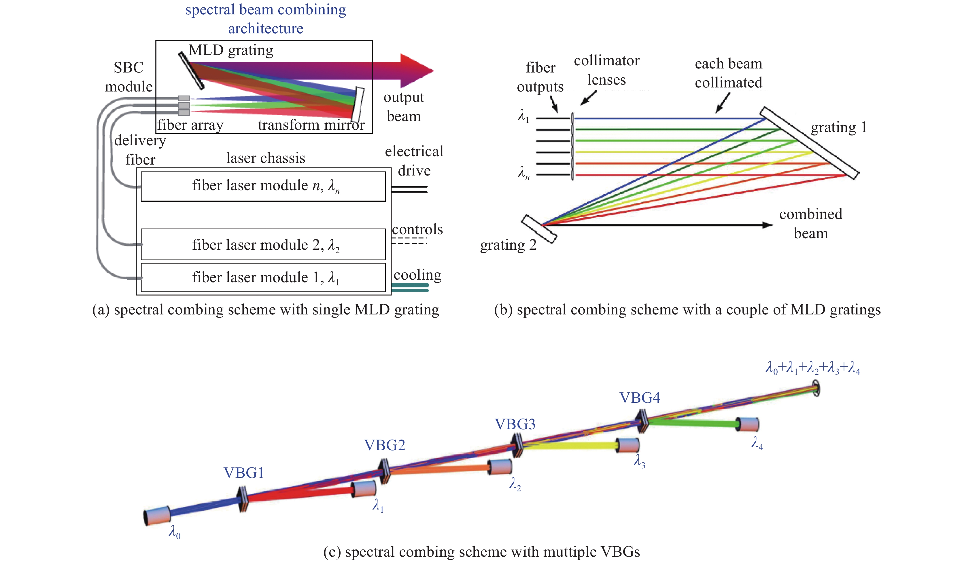
目前基于DOE的光纤激光光谱合成技术有如图1所示的三种方案:使用单个MLD光栅(图1(a))、一对MLD光栅(图1(b))或体布拉格光栅(VBG)图1(c))。其中VBG又可以分为透射式(T-VBG)和反射式(R-VBG),两种原理上是相同的,只是针对不同的应用需求而存在结构上的差异。
除了基于MLD光纤激光光谱合成获得30 kW的成果外,Lockheed Martin公司也在前期进行了双MLD合成的研究,取得了一定成果,在2009年获得了2束光谱合成一束190 W光谱的结果[7]。Fraunhofer研究所则在2011年使用一个偏振无关的MLD光栅实现了4束光谱合成7.3 kW,M2≈4.3的结果[8],谱间距为8 nm。显然,对应Yb-掺杂光纤可以使用约40 nm的增益谱,这样的谱间距限制了进一步定标的能力。美国中佛罗里达大学则使用VBG进行谱合成[9],实现了将5束160 W、线宽<0.1 nm的非保偏子束,合成得到总功率770 W,M2≈1.2的结果,波长间隔为0.5 nm,实现了很高的合成光束的光束质量。国内近几年在光纤激光的光谱合成技术方面也取得较大的进展,总体达到国际先进水平。
一般而言,光纤激光光谱合成过程中的光束质量退化来自如下几个因素:光栅色散、子束光轴的不一致性、光栅上子束光斑未能实现理想重合等。由于高功率光纤激光中存在较严重的非线性效应,其导致光谱展宽或者限制光谱宽度,因此光栅色散是导致该方案中光束质量退化的主要因素。文献[7, 10-11]指出光栅的色散效应是影响合成激光光束质量的重要因素;文献[12]对基于VBG的光谱合成中色散导致光束质量退化进行了理论研究,指出合成激光的光束质量同时受到VBG和入射子束的影响。本文针对一般性的子束光谱线形,对图1所示的三种光谱合成方案中色散导致光束质量退化进行系统物理分析。
一束波长为λ的理想平行光入射到MLD光栅后,其衍射光方向满足如下方程
mλ=d(sinα+sinβ) (1) 式中:m为衍射阶数;d为光栅刻槽间距;α和β分别为入射角和衍射角。本文只关心效率最高的衍射阶数m=−1时的衍射。
那么对于任意一个单色的入射光场
u(x,y,λ) ,这里x,y为垂直于光轴的平面上的坐标,并且记x垂直于光栅刻槽,则光栅衍射后的光场可以表示为u′(x,y,λ)=√cosα/cosβu(−xcosα/cosβ,y,λ) (2) 当一束非单色的光以相同的角度入射在光栅上时,色散导致的出射角偏移为
Δβ=Δλ/dcosβ 因此需要在式(2)中附加一个倾斜因子
u′(x,y,λ0+Δλ)=√cosα/cosβeikΔλx/dcosβu(−xcosα/cosβ,y,λ0) (3) 式中:λ0为入射光谱的中心波长;Δλ为光谱的半高全宽(FWHM)。
基于单个MLD光栅的光谱合成原理示意如图1(a)所示,这里光谱色散造成的光束质量退化可以利用如下式子进行严格求解。记光束的光谱线型为ρ(λ),MLD对准中心波长λ0,认为所有波长的光在较窄谱段内其空间分布都一样,则可以将入射光场写为
U(x,y,λ)=√ρ(λ)u(x,y) 那么使用式(3),任意光束经过一块MLD光栅衍射后的远场为
Uf(ξ,y,λ)=√ρ(λ)U(0)f′(ξ−(λ−λ0)f′/dcosα,y) (4) 这里
U(0)f′ 是以u(x,y,λ) 为出射场计算的焦距为L的远场。通过计算用二阶矩表示的远场发射角,则色散造成的光束质量退化为M2SBC=w0θλ/π=M2√1+1θ20d2cos2αP∫dλ×ρ(λ)(λ−λ0)2 (5) 式中:θ0为波长λ0对应的单频光的远场发射角;w0为单频光的近场二阶矩;M2为没有光栅衍射的光束质量。式(5)表明光谱合成中光栅色散造成的光束质量退化与光束的二阶矩全宽有关、而与半高全宽无关。当光谱为高斯谱时[10],光束质量退化为
M2SBC=M2√1+12ln2(Δλdθ0cosα)2 (6) 如果光谱线形为Lorentz谱,由于式(5)中的积分项是发散的,我们将得到一个无穷大的光束质量退化。更一般地,如果光谱分布存在一个较大的底盘,其渐进行为近似于
[(λ−λ0)2+Δλ2]−1 ,式(5)的积分也是发散的,这意味着光谱的边带分布对光束质量退化的影响非常大。下面来分析基于一对MLD光栅的光谱合成中(图1(b))色散导致的光束质量退化。记两块光栅间距为L,并定义
Leff=Lcos2α/cos2β,η=xcosα/cosβ (7) 可证明,经过双光栅衍射后光束近场为
U(ξ,y,λ)=√ρ(λ)ieikL+iϕ√Leffλ∫dηeπi(η−ξ)2/Leffλu(−η+Δx,y) (8) Δx=(λ−λ0)Leff/dcosα,ϕ=π(λ−λ0)2Leff/λd2cos2α (9) 对于我们关心的非相干合成问题,相位因子的影响是不重要的,因此式(8)和式(9)表明,有限谱宽的光束通过双光栅后各个光谱分量产生了一个空间平移,此平移量导致合束后的近场光束尺寸扩展,进而导致光束质量的退化,而且光栅间距越大,光束质量退化越严重。
进一步可验证,如果忽略波长变化对远场的轻微影响,经过双光栅衍射后的远场与不考虑光栅系统的远场完全相同,即远场发散角与光谱分布无关。而当两个光栅间距离很小、且入射光束是轴对称或者光谱关于λ0对称,则近场光斑尺寸可用二阶矩近似地表示为
w2=1P∫dxdy⋅x2∫dλ×ρ(λ)|u(−x+Δx,y)|2=w20+L2effd2cos2αP∫dλ×ρ(λ)(λ−λ0)2 (10) 式中:P是入射光功率。则色散造成的光束质量退化为
M2SBC=wθλ/π=M2√1+L2cos2αw20d2cos4βP∫dλ×ρ(λ)(λ−λ0)2 (11) 当光谱为高斯谱时[7]
M2SBC=M2√1+12ln2(LΔλcosαdw0cos2β)2 (12) 与单MLD光谱合成方式一样,如果光谱线形为Lorentz谱,因为式(11)的积分也是发散的,我们仍将得到一个无穷大的光束质量退化。
根据式(5),对于单MLD光谱合成模式,显然,子束的发散角越小(或光束尺寸越大),则色散造成的光束质量退化越严重。而对于双MLD光谱合成模式,从式(11)可以看到,子束的光束尺寸越大,色散造成光束质量退化越小。此外,将式(11)与式(5)进行对比,可以看到当
w0/L<θ0 时,双MLD光谱合成模式所允许的子束二阶矩全宽要大于单MLD模式,反之亦然。受限于光栅的损伤阈值(~30 kW/cm2),单MLD模式高功率合成时子束尺寸量级约为cm级,因此θ0~100 μrad;而为了压缩波长间距,双MLD模式高功率合成时子束尺寸为1~3 mm,光栅间距量级为m级。因此可知双MLD模式所允许的子束二阶矩全宽可比单MLD模式高一个量级。考虑受激布里渊散射(SBS)的限制,双MLD模式所允许的子束输出功率要显著高于单MLD模式。但由于当前技术条件下,高衍射效率的MLD光栅基本上都是与偏振相关的,如何在保偏条件下实现高功率光纤激光输出仍是目前的技术难题。光束通过VBG衍射实现光谱合成的过程相对MLD光栅而言要复杂得多,因为不但有色散造成的光束质量退化问题,VBG的结构还会显著影响到光束的衍射效率。
光束在VBG中的衍射过程可理解为光波被声波的弹性散射过程,满足微观能量守恒和动量守恒
λd=λi=λ,Kd=Ki−KG⇒sinθi+sinθd=λ/navΛ (13) 式中:
λi,λd 分别为入射光和衍射光的波长;Ki,Kd,KG 分别为入射光、衍射光和光栅栅格波的波矢;θi和θd分别为入射光、衍射光与VBG栅格法线的夹角;Λ为VBG栅格间距,nav为VBG的平均折射率。通过联立能量守恒和动量守恒条件,可以得出Bragg条件Ki⋅KG=|KG|2/2⇒sinθi=sinθd=sinθB=λ/2Λnav (14) 式中:θB为Bragg角。必须指出,当入射光波长或入射角不满足Bragg条件时,能量守恒条件被破坏,即
|Ki|≠|Kd| 。此时可以认为有一部分光的能量被衍射到其他方向。显然式(14)和式(1)取m=1的表达式完全相同,那么色散造成的光束质量退化可以由式(5)来描述。
利用VBG进行光谱合成与利用MLD光栅的最大区别在于:相同的色散量下,VBG的衍射带宽和分离角宽度远小于MLD光栅(图2~3)。
可以看到R-VBG在衍射谱上存在一个平坦区域,因此基于VBG的光谱合成最直接的结构是如图1(c)所示的“逐次添油”式结构。但因为带宽较窄,图1(c)中的VBG都是针对不同波长独立制备的,而且合成n个子束需要n−1个VBG(采用立体合成构型可以减少VBG的数量),要实现高功率激光输出,其光学结构将非常复杂。
2. Yb:YAG板条激光的光谱合成技术
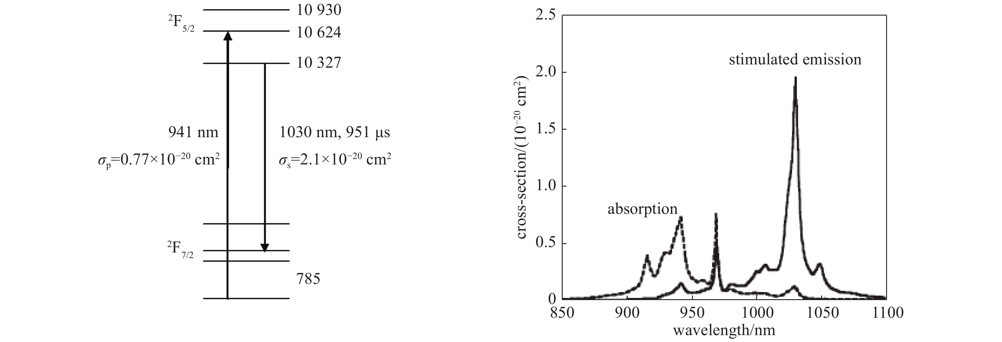
近年来,在高功率固体激光领域,低量子亏损的Yb掺杂材料(图4)显示出比Nd掺杂材料更大的潜力。目前,Yb:YAG薄片激光已经是产生飞秒激光的主要技术途径[13]。2018年,中国工程物理研究院应用电子学研究所研究人员使用三块混合掺杂Yb:YAG板条组成的连续波激光放大器,获得了22.3 kW的高功率激光输出[14];中国科学院理化技术研究所也使用板条晶体在准连续工作模式下取得非常显著的研究成果[15]。为实现更高的功率输出,利用Yb:YAG晶体宽达8 nm的发射光谱(图4),使得将Yb:YAG激光进行光谱合束成为可能。
利用Yb:YAG激光进行光谱合束的方法存在一些技术上的难点。首先,光谱合成要求子束间波长具有一定间距,这就要求Yb:YAG激光在偏移其最佳增益波长时仍然具有较大的增益。室温下Yb:YAG晶体的饱和激光光强约为10 kW/cm2,因此如何保证其在偏移最佳增益波长后实现足够高的光光效率是一个难点。而且Yb:YAG晶体的增益谱相比Yb掺杂光纤要窄得多,而受子束物理间距限制,在较小的合成区间内合成多路子激光较为困难。
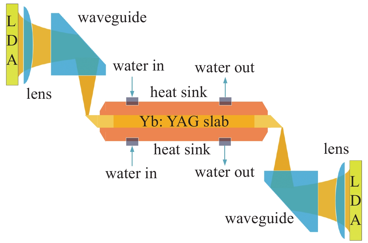
为了克服这些困难,我们设计了如图5所示的腔内光谱合成实验装置[17]。其中增益介质选用了尺寸为176 mm × 33 mm × 3 mm的双端键合Yb:YAG板条,掺杂区长度为150 mm,采用端泵浦结构(图6);半导体泵浦源为两个带有快轴准直镜(FAC)的巴条面阵,每个面阵包含两个由30个巴条组成的叠阵,使用准连续模式泵浦Yb:YAG板条,泵浦脉宽为600 μs,波长为940 nm,巴条在电流为300 A时的峰值功率为300 W;注入板条的泵浦光斑尺寸为28 mm × 2.3 mm,因此板条内泵浦光的最大强度为22 kW/cm2。
图5中A1为8个曲率为−1600 mm的小凹面反射镜组成的阵列,A2为8个焦距为100 mm的小凸透镜组成的阵列;为了和板条厚度(3 mm)相匹配,同时充分利用泵浦区域,每个小反射镜在光谱合成方向(板条宽度)尺寸为2.4 mm,相邻两个小反射镜的间距h=2.5 mm。变换透镜焦距f为1250 mm,与小透镜形成12.5倍扩束,以避免在光栅上功率密度过高。MLD光栅刻线密度为1740 lines/mm,闪耀波长为1030 nm,对应的Littrow角为63.65°,衍射效率为96%,带宽为30 nm;光束在MLD上的入射和出射角分别为69°和60°。优化后的耦合输出镜的反射率为78%。
虽然在图5的结构中存在8个子激光振荡器,但A1中有一个反射镜的光轴指向相对于其他反射镜光轴指向的偏差达到了0.4 mrad,难以形成振荡。根据光栅方程(1),各振荡器输出激光的中心波长偏离1030 nm的波长偏差为
δλn=−ndhfcosα,n=−k+12,−k+32,⋯,k−12 (15) 取小反射镜间隔h为2.5 mm,预计得到的光谱间隔为0.41 nm。
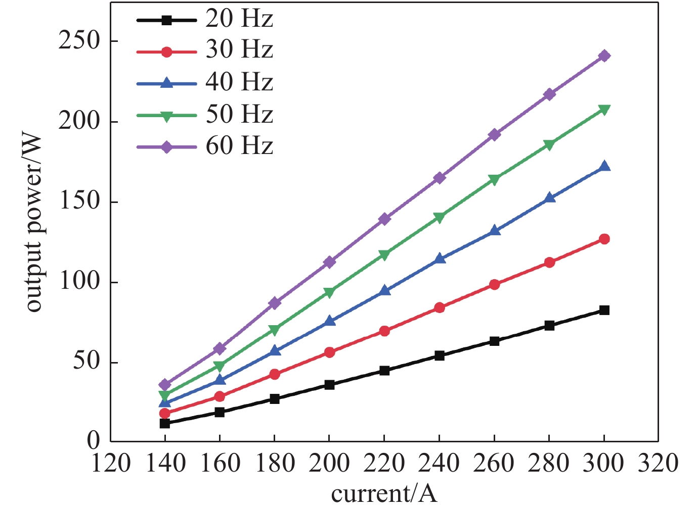
实验中以频率间隔为10 Hz、电流间隔为20 A依次提升泵浦功率,得到的输出功率随电流变化的曲线如图7所示。最终在60 Hz,300 A条件下实现了241 W的光谱合束激光输出,对应的泵浦功率为1300 W。最高泵浦功率时的光光效率仅约为18.5%,这主要是由三个原因导致的:首先,泵浦阵列在达到峰值功率时对应的板条内平均泵浦光强约为17 kW/cm2,远未达到30 kW/cm2的泵浦饱和光强;其次,MLD光栅插入振荡器内部后,会产生约8%的往返损耗,导致输出功率出现较大下降;最后,考虑到A1和A2中小透镜和小反射镜的光束截边效应,激光束和泵浦区的交叠效率只有约70%。
图8给出了利用光纤光谱仪(海洋光学HR4000,光谱分辨率为0.07 nm)在输出功率为241 W时测量到的光谱,这里给出了3帧随机采样的结果。从结果中可以看到,有7个子束形成了激光振荡,光谱间隔约为0.38 nm,合束后整体光谱区间约为2.3 nm,与前述理论分析相吻合。此外,还可以看到光谱分布在时域上存在抖动,但在1029~1031.5 nm区间,板条晶体的整体增益水平都满足要求。必须指出,因为光谱仪的分辨率为0.07 nm,其无法测量到光谱宽度小于0.2 nm以下的精细光谱分布,因此图8中每个子峰的光谱宽度不具有参考价值。
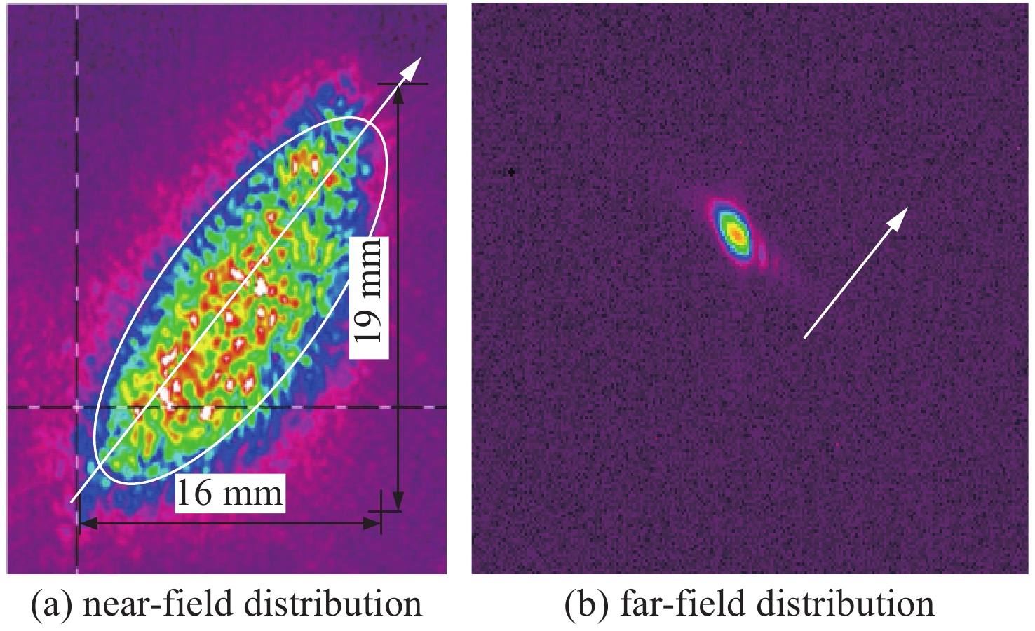
图9给出了在平均输出功率为241 W时,用电荷耦合器件CCD(Spiricon,LBA-FW-SCOR-20)测得的光谱合束后近场和远场的光斑分布。因为板条的宽度方向为垂直方向,MLD的衍射方向为空间倾斜的,所以光斑分布呈现倾斜状。本文使用β因子来评价合成后的光束质量,其定义为:
β=θ/θ′ ,这里θ为实际的光束远场发散角,θ′为理想参考的光束远场发散角。参考光束的近场使用了图9(a)所示的椭圆包络,椭圆的长轴对应于光谱合成方向。计算得到合成方向和非合成方向β因子分别为3.9和4.3,合成后总的光束质量β≈4.1。这表明光栅色散造成的光束质量退化很小,因此子束光谱的二阶矩全宽很窄,这也是固体激光的显著优点。此外,光谱合成过程还在一定程度上抑制了高阶横模(图9(b)),可以看到在非合成方向存在高阶横模的衍射旁瓣),使得光束质量获得一定程度提升。综上,在1029~1031.5 nm的光谱区间内,Yb:YAG板条激光的增益水平未出现显著下降,表明大功率Yb:YAG板条激光具有通过光谱合束技术实现进一步提升输出功率的潜力。需要指出,因为本文只是试图对Yb:YAG板条激光的光谱合成可行性进行原理验证,文中的实验结构并不是优化的。较为理想的技术途径是采用多条板条放大器链路输出不同波长激光,然后再使用MLD光栅进行光谱合成。
3. 半导体激光的光谱合成技术
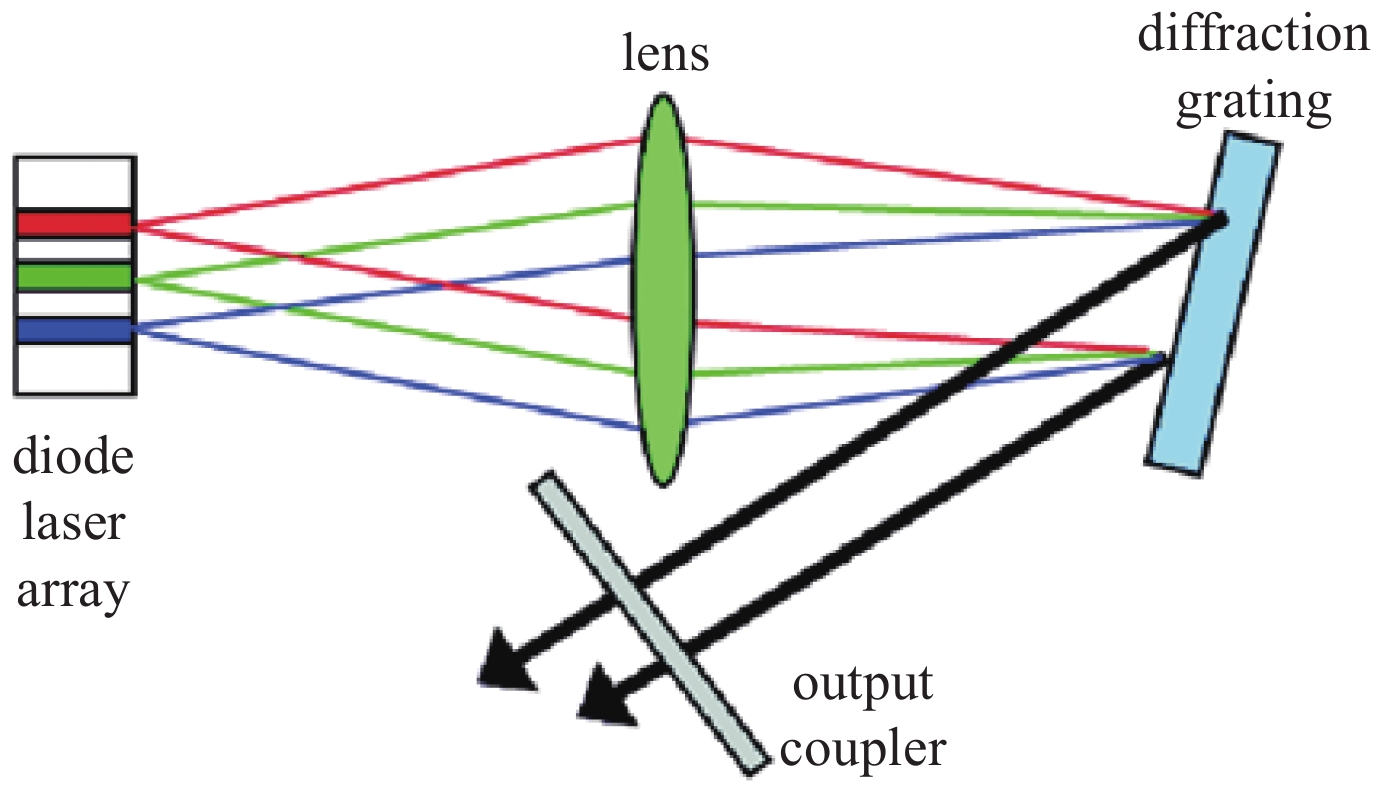
自从2000年麻省理工大学Lincoln实验室首次提出采用光栅-外腔的方法针对半导体激光阵列的外腔光谱合束技术[18]以来,该方法受到极大地重视和关注。经过近二十年的发展,已经成为了当下发展超高亮度半导体激光的最重要技术途径。半导体激光阵列外腔光谱合成原理图如图10所示。
美国的TeraDiode公司走在世界半导体激光光谱合成技术的前列,其于2012年报道了其基于SBC技术实现光束参量积(BPP)为3.75 mm·mrad的直接输出LD光源,输出功率可达2030 W[19-20],这个指标随后提高至4000 W;美国Alfalight则在2012年报道了基于7个光纤耦合输出200 W的SBC模块,作为泵浦源实现了波长1080 nm单模连续1 kW近衍射极限的光纤激光输出[21]。国内开展半导体激光器光谱合束研究的主要有中科院半导体研究所、中国科学院长春光学精密机械研究所、北京工业大学、中国工程物理研究院应用电子学研究所等单位。
前述的多数技术都是针对同一个巴条上的多个发光单元,沿着巴条的慢轴方向进行光谱合成的。但使用该技术途径实现高光束质量高功率激光输出存在两个物理限制:首先,巴条上单个发光单元的输出功率的提升和光束质量存在矛盾,如果增加发光区宽度以提高单个发光点的功率,其光束质量反而会更快地下降。其次,由于“smile”效应,巴条不能太宽,这限制了通过增加发光点数量来提高合成总功率的途径。
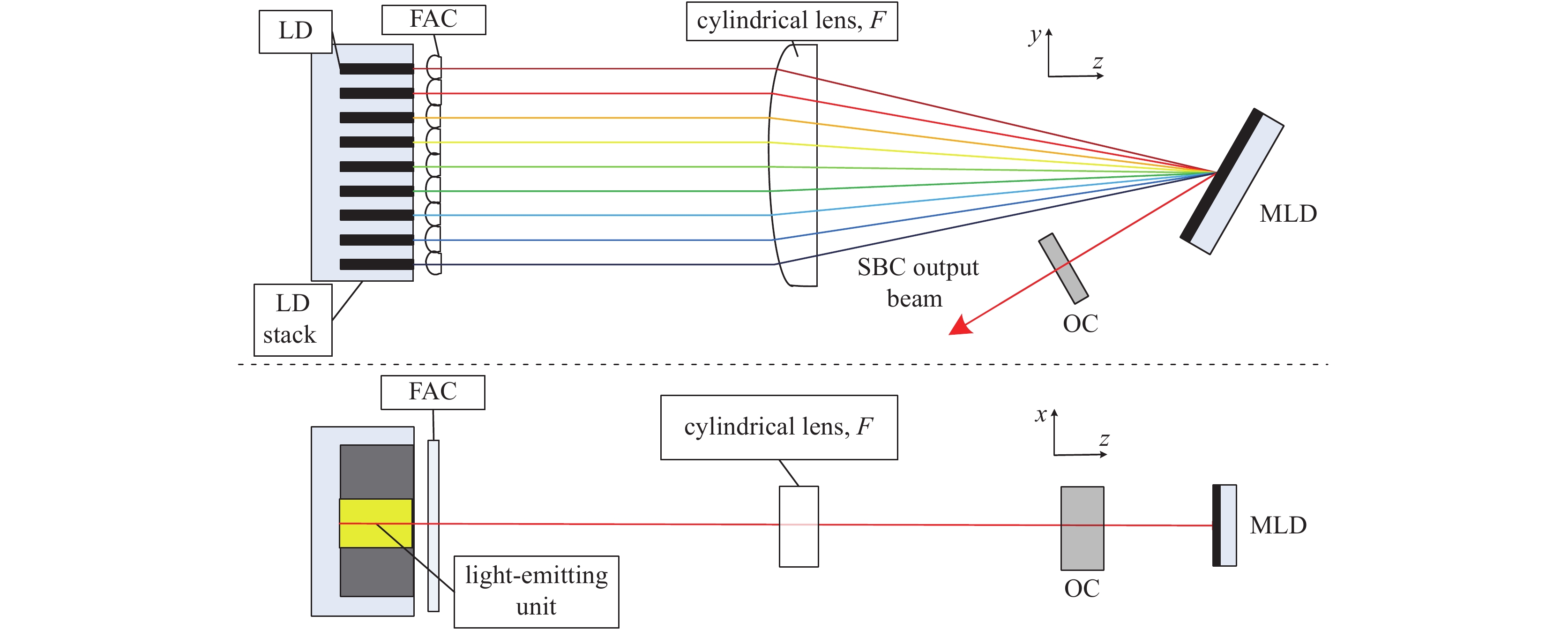
为解决上述问题,我们提出并设计了大模场外腔半导体激光+快轴光谱合成的技术方案,如图11所示,其整体结构是一个立体复合外腔:LD在慢轴方向为5 mm宽“mini”巴条,其上只有一个宽度1 mm的发光点,长度为3 mm,前腔面镀增透膜,后腔面镀高反膜。LD芯片的中心波长为97x nm,后腔面与反射率16%的平面耦合输出镜(OC)形成外腔振荡,腔长为500 mm,通过实现一个大基模体积的外腔振荡[22]来实现发光单元的功率和光束质量的同步提升。在快轴方向,从LD芯片出射的激光经过一组微柱透镜阵列进行准直后,入射到一块焦距为250 mm的柱面变换透镜F上进行聚焦,将MLD光栅(刻线密度为1800 lines/mm,衍射谱区间为955~985 nm)放置在F的焦平面处对聚焦光束进行衍射,最后通过OC实现激光振荡和输出。由于OC只将在轴光束原路反射回到振荡器,不同位置的LD出射激光必须具有不同波长才能实现反馈振荡,因此,此方案的外腔同时实现了三个目标:慢轴方向大模场激光的产生、快轴方向的波长锁定以及快轴方向的光谱合成。
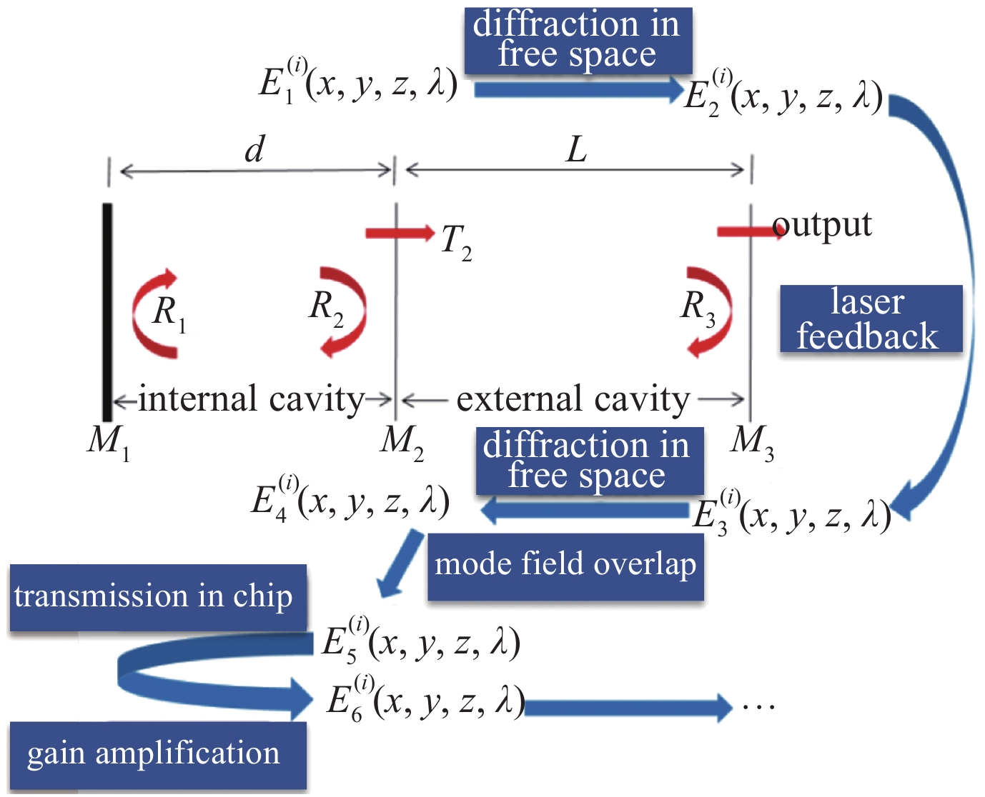
因为目前LD前腔面的透射膜透过率最高只能镀到99%,一般情况下外腔谐振模式和内腔导波模式间将存在模式竞争。因此必须强调,外腔LD的激光动力学过程和固体激光完全不同,也和内腔LD存在较大差异。外腔LD的激光性能特征都是与LD芯片内部的激光动力学过程密切相关的。如图12所示,其物理过程可以概述为:外腔LD出射激光经过自由空间衍射后入射到外腔光学器件上,反射光或衍射光以某些方式沿原光路返回,再次经过自由空间衍射传输后注入LD,激光在LD芯片中经过传输、增益放大、以及与内腔模式竞争过程后再次出射。经过上述过程的多次反馈振荡,外腔LD获得模式特征给定的输出光场。这些过程密切影响到外腔LD对芯片储能的提取效率及输出激光的光束质量。
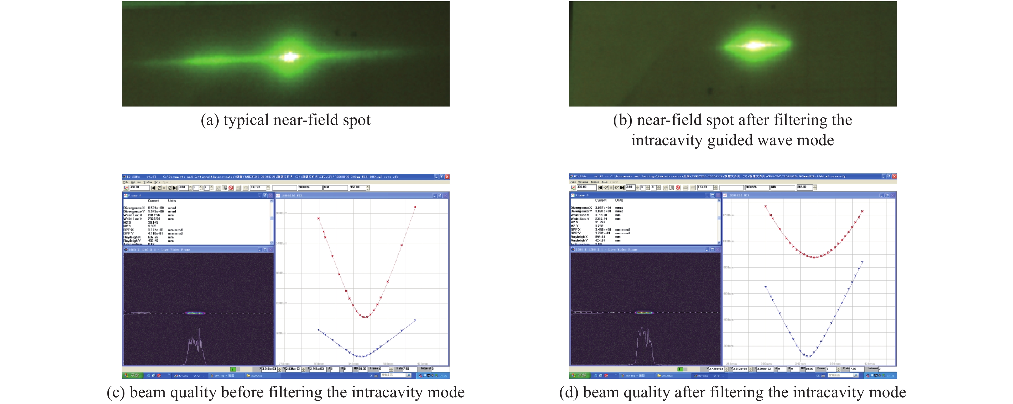
典型准连续工况(电流为40 A、重复频率为160 Hz、脉宽为500 μs)下,实验测量到的单个芯片输出激光的典型近场光斑如图13(a)所示(通过漫反射屏成像),测量到的慢轴光束质量M2≈38.1(图13(c))。从图13(a)可以看到在中心很亮的外腔谐振模式两侧,出现了大发散角的内腔导波模式,这极大地影响了输出激光的光束质量。将内腔导波模式用7 mm宽狭缝光阑滤除后(图13(b)),测得外腔谐振模式的功率占比约为74%,慢轴光束质量M2≈11.2(图13(d)),对应的β≈6.1。与以上情况做对比,没有外腔谐振时,慢轴光束质量M2>100。因此如我们所预期,外腔半导体激光可以非常有效地改善慢轴方向的光束质量。
本文中所使用的微通道冷却器厚度为1.8 mm,实验测量到的输出激光光谱如图14(a)所示,其光谱间距为1.37 nm,与由式(15)给出的理论预期1.43 nm符合得非常好。在CCD上测量到的光谱合束前的近场和光谱合束后的远场分别如图14(b)(已滤除芯片自身的内腔波导模式)和图14(c)所示。远场的光斑倾斜是由于各巴条间存在一定的指向不一致以及巴条与FAC间未能严格平行造成的。计算得到,合束后在慢轴方向β约为6.3,在快轴方向β约1.6,总光束质量
β=0.5(βx2+βy2)1/2≈3.25 。这表明大模场外腔半导体激光+快轴光谱合成的技术途径能够非常有效地改善半导体激光的光束质量,因此该技术在大功率直接应用方面有很大的潜力。4. 结 论
本文对多种全固态激光中的光谱合成技术进行了探讨和研究,包括对光纤激光光谱合成中光谱线型造成的光束质量退化进行了细致物理分析,并展示和讨论了针对Yb:YAG板条光谱合成技术和半导体激光光谱技术的一些创新性研究的结果。
对于光纤激光,探讨了基于单个MLD光栅、一对MLD光栅、多个VBG三种衍射光学元件的光谱合成。建立了光栅色散造成光束质量退化的一般性物理模型,指出光束质量退化决定于子束光谱线型的二阶矩全宽、而非半高全宽,因此光谱线形对光束质量退化有显著的影响。此外,物理模型显示,对于单MLD光谱合成模式,子束的发散角越小(或光束尺寸越大),则色散造成的光束质量退化越严重。而对于双MLD光谱合成模式,子束的光束尺寸越大,色散造成光束质量退化却越小。因此双MLD模式所允许的子束二阶矩全宽可比单MLD模式高一个量级。考虑SBS的限制,双MLD模式所允许的子束输出功率要显著高于单MLD模式。但在当前技术条件下,高衍射效率的MLD光栅基本都是偏振相关的,如何在保偏条件得到足够高功率的光纤激光输出目前仍是技术难题。对于基于VBG的光纤激光光谱合成,因为反射式VBG在衍射谱上存在一个平坦区域,其最佳的结构是如图1(c)那样的“逐次添油”式结构。该结构合成n个子束需要n−1个VBG(采用立体合成构型可以减少VBG的数量),而且不同VBG都是针对不同波长独立制备的,要实现高功率激光输出,其光学结构将非常复杂;进一步考虑到当前工艺水平制备的VBG在高功率下存在较大的热变形,高功率光纤激光光谱合成器件暂时应优选MLD光栅。
进一步实验演示了基于Yb:YAG晶体的板条激光实现光谱合成的原理可行性。通过设计一个基于MLD光栅振荡器内光谱合成装置,实现了7束mm级子激光最高为241 W光谱合成输出,合成后光束质量β因子约4.1,基本达到子激光光束质量水平。实验表明,至少在1029~1031.5 nm光谱区间内,Yb:YAG板条激光的增益水平未出现显著下降,表明大功率Yb:YAG板条激光具有通过光谱合束技术实现功率进一步提升的潜力。
最后,针对LD巴条的慢轴方向进行光谱合成中,同时实现高光束质量、高功率激光输出存在彼此矛盾的物理和技术限制难题,提出并设计了大模场外腔半导体激光+快轴光谱合成的技术。该技术方案在LD的慢轴方向通过实现一个大基模体积的外腔振荡来实现发光单元的功率和光束质量的同步提升;在快轴方向通过外腔腔内光谱合成近一步提升功率。实验结果表明,单就慢轴方向而言,大模体积的外腔谐振将无外腔谐振时的慢轴光束质量从M2>100提升至M2≈11.2(β≈6.1),表明大模体积外腔谐振的半导体激光可以非常有效地改善慢轴光束质量。实验进一步实现了9个大模体积外腔LD芯片沿快轴方向的光谱合成,合成后的光束质量在慢轴方向β约为6.3,在快轴方向β约1.6,表明快轴方向光谱合成造成的光束质量退化是完全可控的。因此该技术途径能够非常有效地改善半导体激光的光束质量,在大功率直接应用方面有很大的潜力。
-
表 1 EIK的主要设计参数
Table 1. Main design parameters of the Ka-band extended interaction klystron(EIK)
frequency/GHz beam voltage/kV beam current/A output power of CW/kW efficiency/% gain/dB 35 10 0.49 1.35 27.5 54 表 2 部分废电子信息
Table 2. Information of part of waste electrons
x position/m y position/m z position/m ux uy uz mass/kg charge/C macro particle charge/C time/s −1.23E−04 −2.81E−05 4.10E−02 −1.28E−03 2.68E−03 0.164 9.10E−31 −1.60E−19 −2.22E−16 2.50E−08 −1.12E−04 −5.39E−05 4.10E−02 −1.83E−03 2.25E−03 0.164 9.10E−31 −1.60E−19 −2.17E−16 2.50E−08 −1.18E−04 −3.67E−05 4.10E−02 9.95E−04 −4.13E−03 0.165 9.10E−31 −1.60E−19 −2.66E−16 2.50E−08 −2.46E−05 −2.33E−04 4.10E−02 −7.46E−03 −9.42E−03 0.164 9.10E−31 −1.60E−19 −1.87E−16 2.50E−08 −9.48E−05 −9.30E−05 4.10E−02 3.41E−03 −2.00E−03 0.164 9.10E−31 −1.60E−19 −2.39E−16 2.50E−08 −9.44E−05 −9.35E−05 4.10E−02 3.37E−03 −2.01E−03 0.164 9.10E−31 −1.60E−19 −2.39E−16 2.50E−08 表 3 单级降压收集极的设计参数
Table 3. Design parameters of the one-stage depressed collector
drift length/mm drift entrance radius/mm drift exit radius/mm collector length/mm collector entrance radius/mm collector exit radius/mm 8 0.45 0.6 71.5 0.9 5 表 4 单级降压收集极的回收效率、回流率与压降的关系
Table 4. Relationship between recovery efficiency, reflux rate and voltage drop of the one-stage depressed collector
voltage/kV recovery efficiency/% electron reflux rate/% −3.0 26 0 −4.0 40 0 −4.1 41 0.02 −4.2 43 1.00 −4.3 44 1.05 −5.0 54 3.20 −6.0 68 4.60 表 5 初始两级降压收集极的设计参数
Table 5. Design parameters of initial two-stage depressed collector
length/mm entrance radius/mm exit radius/mm drift one-stage collector two-stage collector drift one-stage collector two-stage collector drift one-stage collector two-stage collector 8 31 40 0.35 0.9 3 0.6 5 5 表 6 改进后的两级降压收集极设计参数
Table 6. Design parameters of improved two-stage depressed collector
length/mm entrance radius/mm exit radius/mm drift one-stage collector two-stage collector drift one-stage collector two-stage collector drift one-stage collector two-stage collector 8 13.5 27.5 0.35 0.7 6 0.6 5 5 表 7 优化的各级压降及回收效率
Table 7. Design parameters of improved two-stage depressed collector
voltage of the first stage/kV voltage of the second stage/kV recovery efficiency/% −4.1 −10 68.8 −3.7 −9 49.2 −3.0 −8 53.6 −2.1 −7 38.7 −1.5 −6 43.1 −0.6 −5 37.3 −4.0 −4 40.0 表 8 不同初始条件下的回收效率和整管效率
Table 8. Recovery efficiency and tube efficiency under different initial conditions
initial condition recovery efficiency/% tube efficiency/% PID 1 72.4 57.8 PID 2 70.9 56.1 PID 3 64.5 51.6 PID 4 68.8 54.8 PID 5 67.9 54.1 PID 6 66.1 52.8 PID 7 71.3 56.9 PID 8 72.8 58.2 -
[1] 洪伟, 余超, 陈继新, 等. 毫米波与太赫兹技术[J]. 中国科学: 信息科学, 2016, 46(8):1086-1107. (Hong Wei, Yu Chao, Chen Jixin, et al. Millimeter wave and terahertz technology[J]. Scientia Sinica Informationis, 2016, 46(8): 1086-1107 doi: 10.1360/N112016-00069 [2] 丁耀根. 功率速调管的技术现状和最新进展[J]. 真空电子技术, 2020(1):1-25. (Ding Yaogen. The technical status and latest progress of high-power klystron[J]. Vacuum Electronic, 2020(1): 1-25 [3] Srivastava V, Sinha A K, Josh S N, et al. Design of four-stage depressed collector for a high efficiency helix TWT[C]//Third IEEE International Vacuum Electronics Conference. 2002: 257-258. [4] Chodorow M, Wessel-Berg T. A high-efficiency klystron with distributed interaction[J]. IRE Trans Electron Devices, 1961, 8(1): 44-15. doi: 10.1109/T-ED.1961.14708 [5] 张长青, 阮存军, 王树忠, 等. 梯形结构高功率扩展互作用速调管[J]. 红外与毫米波学报, 2015, 34(3):307-313. (Zhang Changqing, Ruan Cunjun, Wang Shuzhong, et al. High-power extended-interaction klystron with ladder-type structure[J]. Journal of Infrared and Millimeter Waves, 2015, 34(3): 307-313 doi: 10.11972/j.issn.1001-9014.2015.03.010 [6] 丁耀根. 大功率速调管的设计制造与应用[M]. 北京: 国防工业出版社, 2010.Ding Yaogen. Design, manufacture and application of high-power klystrons[M]. Beijing: National Defense Industry Press, 2010 [7] 刘宇荣, 刘斌, 王大明. 大功率行波管两级降压收集极的设计[J]. 强激光与粒子束, 2017, 29:103002. (Liu Yurong, Liu Bin, Wang Daming. Design of two stage depressed collector for high-power traveling wave tube[J]. High Power Laser and Particle Beams, 2017, 29: 103002 doi: 10.11884/HPLPB201729.170144 [8] Gao Dongping, Ding Yaogen, Zhang Zhaochuan, et al. Design of a continuous wave Ka-band extended interaction klystron[C]//2014 IEEE International Vacuum Electronics Conference. 2014. [9] Ding Haibing, Tang Liang, Song Yihao, et al. Design of a Ka-band CW extended interaction klystron[C]//2018 IEEE International Vacuum Electronics Conference. 2018. [10] Gilmour A S. Klystron, traveling wave tubes, magnetrons, crossed-field amplifiers, and gyrotrons[M]. Beijing: National Defense Industry Press, 2012. [11] 寇建勇, 闫铁昌, 盛兴. 用Opera3D计算速调管多级降压收集极[J]. 真空电子技术, 2017(6):71-74. (Kou Jianyong, Yan Tiechang, Sheng Xing. Simulation of MDCs for klystrons using Opera 3D[J]. Vacuum Electronic, 2017(6): 71-74 [12] 刘明辉. 多级降压收集极的模拟与实验研究[D]. 成都: 电子科技大学, 2012: 10-25.Liu Minghui. Simulation and experimental study of multistage depressed collector[D]. Chengdu: University of Electronic Science and Technology, 2012: 10-25 [13] 郑志清, 罗勇, 蒋伟, 等. 回旋行波管收集极的热分析[J]. 强激光与粒子束, 2013, 25(3):721-726. (Zheng Zhiqing, Luo Yong, Jiang Wei, et al. Thermal analysis of gyrotron traveling-wave tube collector[J]. High Power Laser and Particle Beams, 2013, 25(3): 721-726 doi: 10.3788/HPLPB20132503.0721 [14] 白现臣, 杨建华, 张建德, 等. 电子束收集极对大间隙速调管输出腔效率的影响[J]. 强激光与粒子束, 2011, 23(6):1625-1628. (Bai Xianchen, Yang Jianhua, Zhang Jiande, et al. Influence of electron beam collector on output cavity efficiency of wide-gap klystron amplifier[J]. High Power Laser and Particle Beams, 2011, 23(6): 1625-1628 doi: 10.3788/HPLPB20112306.1625 [15] 耿志辉, 刘濮鲲, 粟亦农, 等. W波段连续波30 kW回旋振荡管高频系统和收集极的设计[J]. 强激光与粒子束, 2011, 23(11):3036-3038. (Geng Zhihui, Liu Pukun, Su Yinong, et al. Design of interaction circuit and collector for W-band continuous wave 30 kW gyrotron oscillator[J]. High Power Laser and Particle Beams, 2011, 23(11): 3036-3038 doi: 10.3788/HPLPB20112311.3036 期刊类型引用(1)
1. 周朴,粟荣涛,李灿,马阎星,张雨秋,李俊,吴坚,王小林,冷进勇. 高功率光纤激光的光束合成:进展、动向与展望(特邀). 中国激光. 2024(19): 45-60 .  百度学术
百度学术其他类型引用(1)
-


 下载:
下载:


 下载:
下载:
