Influence of ion beam perveance condition on grids erosion for ion thruster
-
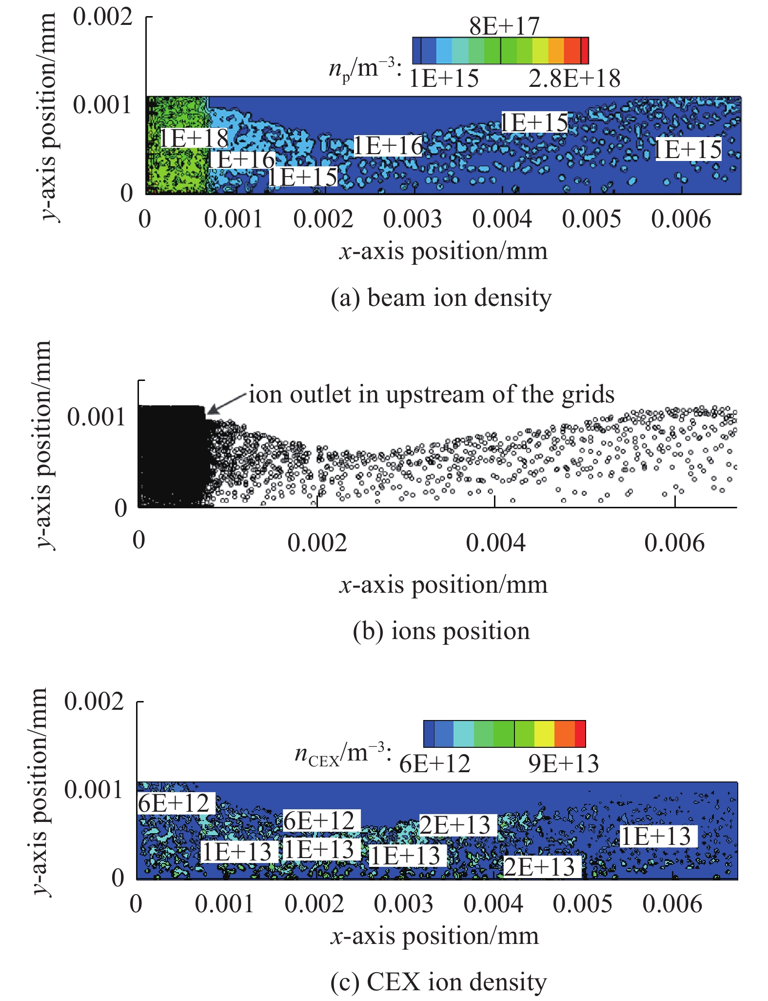
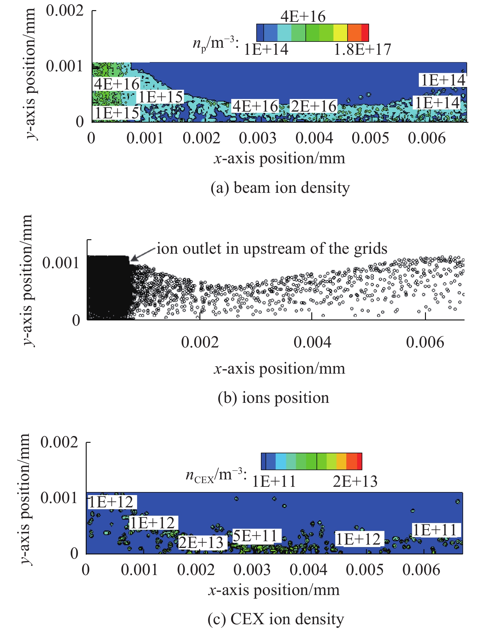
摘要: 为了研究30 cm离子推力器束流引出状态对栅极刻蚀的影响,建立了束流引出模型,并采用PIC-MCC方法对CEX离子造成的栅极腐蚀速率进行了计算,最后将计算结果与1500 h寿命试验结果进行比对分析。结果显示:束流正常聚焦时,在3 kW和5 kW两种工作模式下,加速栅和减速栅的质量刻蚀速率分别为(1.11~1.72)×10−15 kg/s及(1.22~1.26)×10−17 kg/s。在5 kW工况下,当屏栅上游等离子体密度达到4.03×10¹⁷ m−3时,束流出现欠聚焦现象,此时加速栅和减速栅的最大离子刻蚀速率分别为4.33×10⁻¹⁵ kg/s和4.02×10−15 kg/s;在3 kW工况下,当屏栅上游等离子体密度达到0.22×10¹⁷ m−3时,束流出现过聚焦现象,此时加速栅和减速栅的最大离子刻蚀速率分别为3.24×10⁻¹⁵ kg/s和5.01×10−15 kg/s。寿命试验结果表明,加速栅孔质量刻蚀速率的计算值与试验值比对误差较小,而由于束流离子对减速栅孔的直接轰击,导致减速栅孔刻蚀速率的计算值和试验值差异极大。经研究认为,对屏栅小孔采用变孔径设计,是降低当束流处于欠聚焦或过聚焦状态下,CEX离子造成加速栅孔和减速栅孔刻蚀速率,并提升推力器工作寿命的有效措施。Abstract: To study the influence of ion beam perveance condition on the grids erosion velocity for 30 cm diameter ion thruster, we established a beam perveance model and calculated the grids erosion velocity caused by CEX (charge exchange) ions by PIC-MCC method, and then compared and analyzed the calculation results with 1500 h short time life test results. The results show that under the normal beam perveance condition, the mass erosion velocity of the accelerator grid and the decelerator grid are (1.11−1.72)×10−15 kg/s and (1.22−1.26)×10−17 kg/s in 3 kW and 5 kW working modes, respectively. Under 5 kW working mode, when the upstream plasma density of the screen grid reaches 4.03×10¹⁷ m−3, the beam is under perveance condition, and the maximum ion erosion velocity of the accelerator grid and the decelerator grid is about 4.33×10⁻¹⁵ kg/s and 4.02×10⁻¹⁵ kg/s respectively. Under 3 kW working mode, when the upstream plasma density of the screen grid reaches 0.22×10¹⁷ m−3, the beam is in over perveance condition. Meanwhile, the maximum ion erosion velocity of the accelerator grid and the decelerator grid is about 3.24×10⁻¹⁵ kg/s and 5.01×10⁻¹⁵ kg/s respectively. The life test results show that the calculation value of mass erosion velocity of the accelerator grid hole has a small error to the test value. However, the calculation results of erosion velocity of the decelerator grid hole differ greatly from the test results, which is mainly because of the direct bombardment of the beam ions on the decelerator grid hole. From the current research conclusions, it is considered that the variable aperture design for the screen grid hole is an effective measure to reduce the erosion velocity of the accelerator grid hole and the decelerator grid hole caused by CEX ions when the beam is in under or over perveance condition. In addition, variable aperture design of the grids can significantly improve the working life of the thruster.
-
Key words:
- ion thruster /
- grid erosion /
- ion beam /
- perveance condition
-
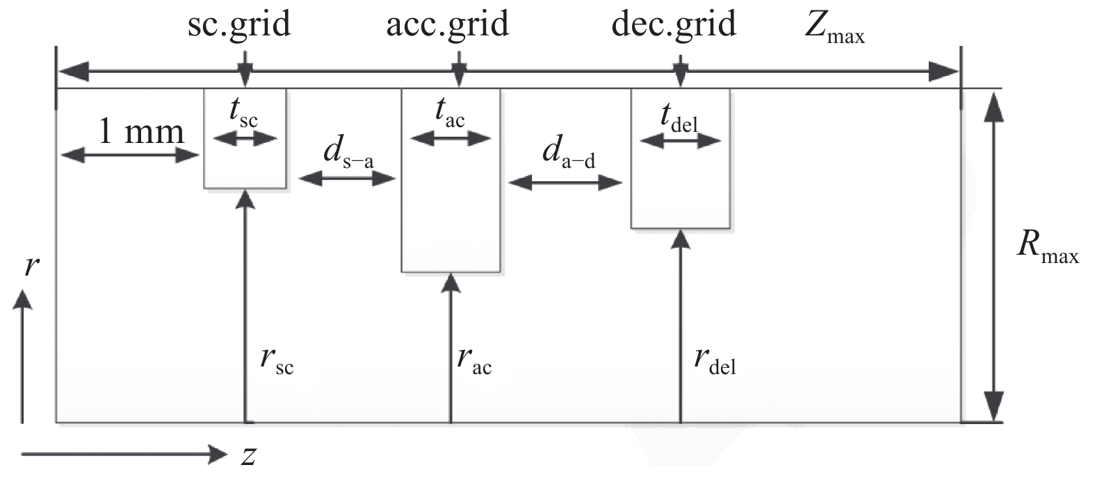
表 1 PIC-MCC方法的关键参数设置
Table 1. Parameters set for simulation by PIC-MCC method
rsc/mm rac/mm tsc/mm tac/mm ds−a/mm rdel/mm tdel/mm Vacc/V 0.95 0.55 0.40 0.50 1 0.65 0.5 −400 Vp/V Ti/K Teu/eV Ted/eV n0/m−3 Vsc/V da−d/mm Vdel/V 37 600 4.5 1.50 − 1200 0.9 0 表 2 离子推力器不同工作模式的输入条件
Table 2. Input parameters of ion thruster in different work mode
work mode anode mass flow/(kg·s−1) cathode mass flow/(kg·s−1) total mass flow/(mg·s−1) anode voltage/V 3 kW 1.97 0.38 2.35 32 5 kW 5.37 0.26 5.63 30.5 表 3 栅极上游中性原子密度分布
Table 3. Neutral density in upstream of the grids
work mode n0/m−3 n01/m−3 anode voltage/V screen grid voltage/V accelerator grid voltage/V 3 kW 1.42×10¹⁷ 8.75×10¹⁷ 32 1415 −220 5 kW 3.36×10¹⁷ 2.11×10¹⁸ 30.5 1165 −400 表 4 不同模式下的刻蚀速率仿真计算结果
Table 4. Simulation results of erosion velocity in different work mode
work mode erosion velocity of acc. grid/(kg·s−1) erosion velocity of dec. grid/(kg·s−1) 3 kW 1.11×10⁻¹⁵ 1.22×10⁻¹⁷ 5 kW 1.72×10⁻¹⁵ 1.26×10⁻¹⁷ -
[1] Sun Mingming, Zheng Yi, Geng Hai. Grid gap variation of ion thruster during start-up in orbit[J]. IEEE Trans Plasma Science, 2020, 48(2): 455-461. [2] Hayakawa Y, Yoshida H, Miyazaki K, et al. Validation of an ion-thruster grid thermal model with experiments[R]. AIAA Paper 2010-6946. [3] Haag T. Mechanical design of carbon ion optics[R]. AIAA Paper 2005-4408. [4] Brophy J, Katz I, Polk J, et al. Numerical simulations of ion thruster accelerator grid erosion[R]. AIAA Paper 2002-4261. [5] Chien K R, Tighe W, Bond T, et al. An overview of electric propulsion at L-3 communications, Electron Technologies Inc[R]. AIAA Paper 2006-4322. [6] Goebel D, Martinez-Lavin M, Bond T, et al. Performance of XIPS electric propulsion in station keeping of the Boeing 702 spacecraft[R]. AIAA Paper 2002-4348. [7] Noord J. Lifetime assessment of the NEXT ion thruster[R]. AIAA Paper 2007-5274. [8] Hayashi M. Determination of electron-xenon total excitation cross-section[J]. Journal of Physics D: Applied Physics, 1983, 16(1): 581-589. [9] Sun Mingming, Wang Liang, Yang Junhai, et al. Study on the key factor of the triple grids’ lifetime for LIPS-300 ion thruster[J]. Plasma Science and Technology, 2018, 20: 045504. [10] 孙明明, 耿海, 龙建飞, 等. 不同环境温度对30 cm离子推力器三栅极组件的离子刻蚀速率影响分析[J]. 推进技术, 2020, 41(1):121-131. (Sun Mingming, Geng Hai, Long Jianfei, et al. Study on the influence of different ambient temperature on the ion erosion rate for the triple grid of 30 cm diameter ion thruster[J]. Journal of Propulsion Technology, 2020, 41(1): 121-131 [11] Goebel D, Schneider A. High voltage breakdown and conditioning of carbon and molybdenum electrodes[J]. IEEE Trans Plasma Science, 2005, 33(4): 1136-1148. [12] Miller J, Pullins S, Levandier D, et al. Xenon charge cross section for electrostatic thruster models[J]. Journal of Applied Physics, 2002, 91(3): 984-991. [13] Katz I, Anderson J, Polk J, et al. One dimensional hollow cathode model[J]. Journal of Propulsion and Power, 2003, 19(4): 595-600. [14] Mikellides I, Katz I, Mandell M. A 1-D model of the Hall-effect thruster with an exhaust region[R]. AIAA Paper 2001-3505 [15] Chen Juanjuan, Zhang Tianping, Geng Hai, et al. Analysis of numerical simulation results of LIPS-200 lifetime experiments[J]. Plasma Science and Technology, 2016, 18(6): 611-616. [16] Goebel D, Jameson K, Watkins R, et al. Cathode and keeper plasma measurements using an ultra-fast miniature scanning probe[R]. AIAA Paper 2004-3430 [17] 贺武生, 孙安邦, 毛根旺, 等. 离子推力器放电腔数值模拟[J]. 强激光与粒子束, 2010, 22(12):3020-3024. (He Wusheng, Sun Anbang, Mao Genwang, et al. Numerical simulation of ion thruster discharge chamber[J]. High Power Laser and Particle Beams, 2010, 22(12): 3020-3024 [18] 温正, 钟凌伟, 王一白, 等. 离子推力器加速栅极离子运动规律的数值研究[J]. 强激光与粒子束, 2011, 23(6):1640-1645. (Wen Zheng, Zhong Lingwei, Wang Yibai, et al. Three-dimensional numerical study on motion laws of ions in ion thruster optics[J]. High Power Laser and Particle Beams, 2011, 23(6): 1640-1645 -


 下载:
下载:
