

Generation and propagation characteristics of plasma applied to pulsed metal ion plasma thruster
-
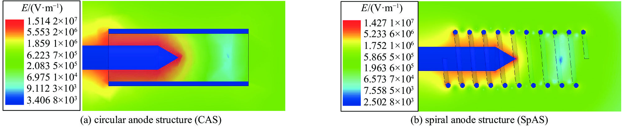
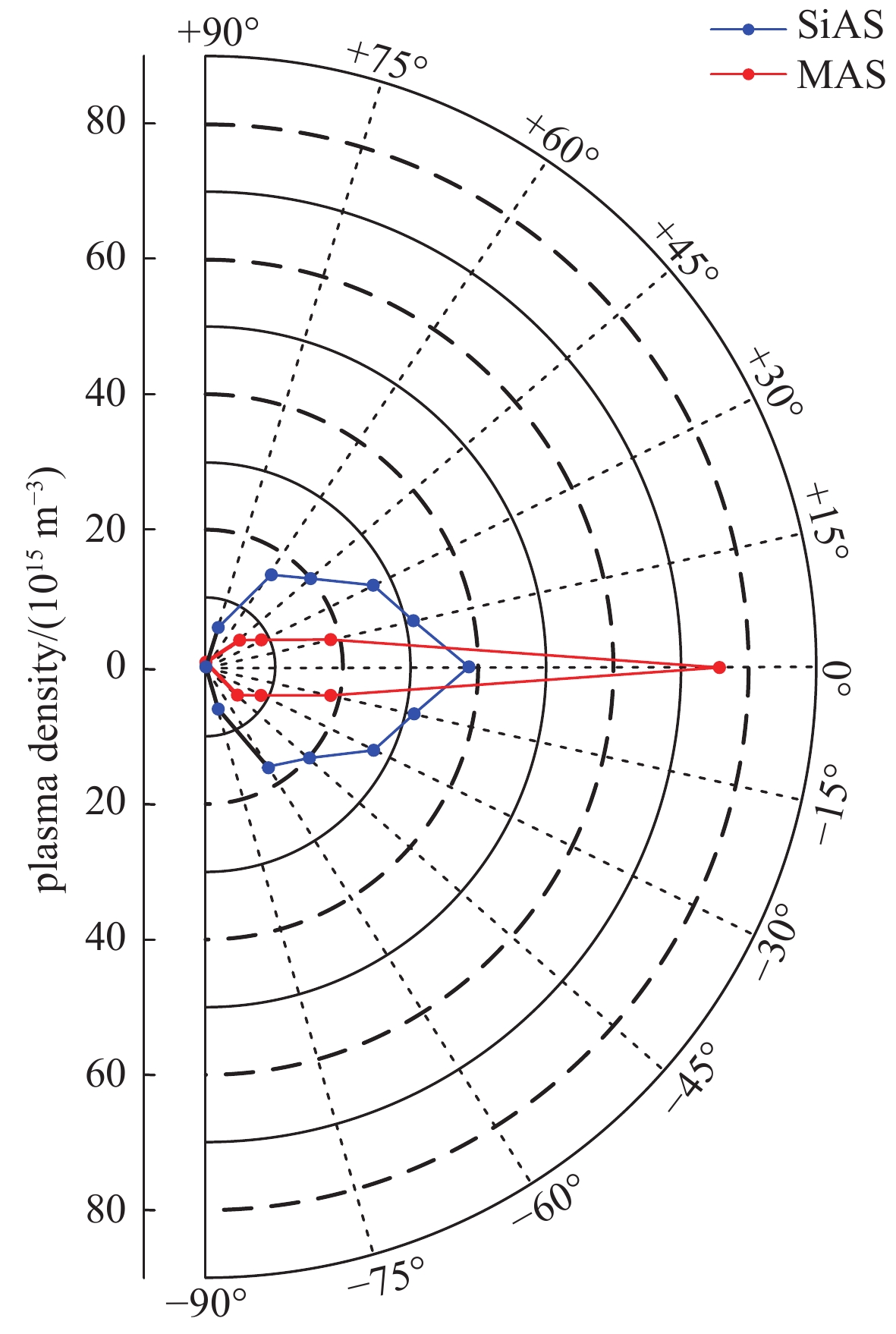
摘要: 综述了不同阳极结构脉冲金属离子等离子体推进器的放电特性、等离子体生成及传播特性。首先,讨论了一种带有绝缘套筒的裸阳极推进器结构。对比分析了无、有绝缘套筒的裸阳极推进器的等离子体生成及传播特性的区别。结果表明,绝缘套筒阻碍了阴极近旁带电粒子的径向运动,提高了沿绝缘套筒轴向喷射出去的等离子体的喷射性能。此外,发现采用裸阳极推进器结构放电过程中会有大量带电粒子进入阳极。其次,讨论了一种绝缘阳极推进器结构。结果表明,采用绝缘阳极结构进一步提高了沿绝缘套筒轴向喷射出去的等离子体密度。但是,与裸阳极推进器结构相比,等离子体的生成量减少。再次,讨论了一种微孔绝缘阳极推进器结构。结果表明,与裸阳极推进器结构相比,采用微孔绝缘阳极推进器结构生成的等离子体的密度峰值和传播速度峰值分别提高了12.6倍、3.9倍。最后,分别讨论了一种螺旋阳极推进器结构和一种多阳极推进器结构。结果表明,这两种推进器结构分别利用放电过程中形成的自磁场及电场有效提高了等离子体羽流的定向喷射性能。本研究可以为金属等离子体喷射性能的提高以及脉冲金属离子等离子体推进器的设计提供支持。Abstract: In this paper, discharge characteristics, plasma generation and propagation characteristics of pulsed metal ion plasma thruster (PMIPT) using different anode structures are reviewed. First of all, a PMIPT using an exposed anode structure with an insulating sleeve (EASIS) is discussed. Differences in plasma generation and propagation characteristics between the EASIS-PMIPT and the PMIPT using an exposed anode structure without an insulating sleeve (EAS-PMIPT) are analyzed. Results show that the insulating sleeve blocks radial diffusion of generated charged particles near cathode, and improves the ejection performance of plasma. In addition, it is found that a large number of charged particles enters anode during discharge with an exposed anode (EA). Then, a PMIPT using an insulated anode structure (IAS) is discussed. Results indicate that peak density of plasma ejected along axial direction of insulating sleeve is further increased by using an IAS. However, compared with the PMIPT with an EA, production of plasma is reduced. Furthermore, a PMIPT using an IAS with a micropore (IASM) is discussed. It is revealed that, compared with the PMIPT with an EA, plasma peak density and propagation velocity when adopting an IASM increase by 12.6 times and 3.9 times respectively. Eventually, PMIPT structures with a spiral anode structure (SpAS) and a multi-anode structure (MAS) are discussed respectively. Results show that for the two thrusters, directional ejection performance of plasma plumes are effectively improved by using the self-magnetic field and electric field during discharge respectively. This study will provide support for improvement of metal plasma ejection performance and the design of a PMIPT.
-
真空条件下,电子通过射频场的加速作用,在金属表面间激发二次电子发射和倍增,二次电子倍增到一定程度产生雪崩效应,形成微放电效应[1-3]。微放电效应研究早在20世纪初已经开始,微放电效应的早期研究主要集中在一些平板类电极和传输线等器件的微放电机理分析工作[4-6]。随着航天技术发展,微波器件的结构更加复杂,功率密度越来越高,空间微波部件发生微放电的可能性大大增加[7-9],卫星通信系统的主要组成部件如输出多工器、波导腔体滤波器和天线馈源等发生微放电现象,易造成卫星系统性功能异常,空间微放电效应已成为制约高通量空间通信技术发展的重要因素[10-12]。国内外如美国航空与航天局(NASA)、欧洲航天局(ESA)、西安交通大学、东南大学和航天五院西安分院等研究机构对微放电的危害越来越重视,通过理论分析和数值模拟等微放电阈值分析方法对大功率微波部件的微放电阈值评估开展研究工作[13-16],对于理论分析和数值模拟方法获得的微放电阈值可通过微放电实验对其准确性进行验证[17-18]。
航天器大功率微波部件易发生双金属表面微放电效应,双金属表面微放电效应的发生从机理上需要同时具备以下四个条件:真空条件,种子电子,材料二次电子发射系数大于1和电子的渡越时间是微波信号半周期的奇数倍,才能实现二次电子在两金属表面间的倍增。自由电子的存在是发生微放电的必要条件,导致微波器件发生微放电现象是电子倍增的结果,种子电子的存在对微放电效应的发生至关重要。在地面实验室研究和测试微波器件微放电效应时,需要将种子电子加载到微波器件[19],常用的方法是在微波器件外部贴敷放射源,如铯源和锶源[20-21],利用放射源的自发裂变产生的各种能量电子和其它裂变粒子与器件材料相互作用发射出来的初始电子作为种子电子。由于放射源的自发裂变反应固定,同时放射源的自发裂变活度有限,这种方式提供的种子电子能量和通量基本不可控,出射电子的通量有限,不能给出定量的种子电子参数,只能从定性的角度模拟微波器件微放电效应,难以模拟大功率微波器件遭受如空间强流电子束诱发的微放电现象,缺乏强流电子束诱发大功率微波器件的微放电规律研究。
本文提出了一种利用电子枪提供空间电子作为种子电子开展微放电研究的实验方法,通过设计特殊波导,将种子电子入射到特殊波导内,在波导内通入大功率微波信号,利用检波器和示波器分别检测透射和反射波形,观测到电子诱发大功率微波器件发生微放电现象。
1. 理论计算
本研究以矩形波导作为微放电效应发生的器件对象,现从理论上对发生微放电现象需要的微波信号功率进行计算,假设以两金属平板之间加
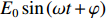
E0sin(ωt+φ) 射频微波信号发生微放电为例,计算微放电的阈值电压。从电子运动方程着手,两平板间电子运动方程为
md2xdt2=eE0sin(ωt+φ) (1) 式中:m为电子的质量,e为电子的电量,x为电子位移,
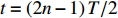
E0 为微波信号电场强度,ω为微波信号角频率,φ为微波信号初始相位。电子在两金属平板微波信号(周期T)作用下,电子渡越时间需要满足微波半周期的奇数倍,即t=(2n−1)T/2 ,其中n=1,2,3⋯ ,才会发生微放电现象,在上述时间段内对式(1)进行两次积分,即可求得两平板间的击穿电压V=E0d=m(2π fd)2e[(2n−1)π cosφ+2sinφ] (2) 其中射频微波频率为f(GHz),两平板间隙宽度为d(mm)。从式(2)可以看出,微放电阈值与微波信号的频率和表面间隙尺寸之积(fd)有关。利用上述方程,结合实际测量结果,建立计算机仿真模型进行计算,可得到不同材质平板间微放电敏感曲线。图1所示为欧洲航天局(ESA)通过计算模型得到的微放电敏感性曲线,该阈值曲线是进行空间波导部件设计时的重要参考标准。
 图 1 微放电间隙电压与fd的关系曲线[14],其中射频频率为f(GHz),间隙宽度为d(mm)Figure 1. Dependence of the gap voltage on the product of the frequency and gap separation (fd). Here, f is the frequency in GHz and d is the gap separation in mm
对于频率f为9.7 GHz微波信号,特殊X波段矩形波导结构尺寸宽边a设为22.86 mm,窄边b设为1 mm,通过矩形波导TEmn和TMmn各模式的截止频率计算公式
fcTEmn=fcTMmn=c2π √(mπa)2+(nπb)2 (3) 得到前5个波导模式对应截止频率分别为:
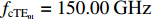
fcTE10=6.56GHz ,fcTE20=13.12GHz ,fcTE01=150.00GHz ,fcTE10=6.56GHz ,fcTE11=fcTM11=150.14GHz 和fcTE21=150.57GHz ,其中c为光速。对于频率为9.7 GHz的微波信号在该矩形波导结构尺寸a和b下,将仅以TE10单一基模传输,不存在其他高阶模式。对于矩形波导TE10模式,矩形波导内的电场方向垂直于长边,因而发生微放电对应的两金属平板的间距则为b,因而fb约为10 GHz·mm,根据微放电的电压阈值与微波信号的频率和部件间隙尺寸的关系,对于铜波导材料,从图1可以看到,发生微放电最低间隙电压值Vth约为900 V,则电场强度Em为
Em=Vth/b=900kV/m (4) 再根据TE10模矩形波导内脉冲功率容限计算公式
P=ab480π E2m√1−(c2af)2 (5) 将a、b、Em、f代入上述公式,得到矩形波导中TE10模微放电阈值功率Pth为9.03 kW,因而对于上述结构尺寸的特殊X波段矩形波导,发生微放电效应的微波峰值功率需大于9.03 kW。下面将采用中心频率为9.7 GHz,带宽为100 MHz,峰值功率10 kW的X波段微波源对该电子诱发矩形波导微放电进行实验验证。
2. 实 验
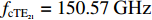
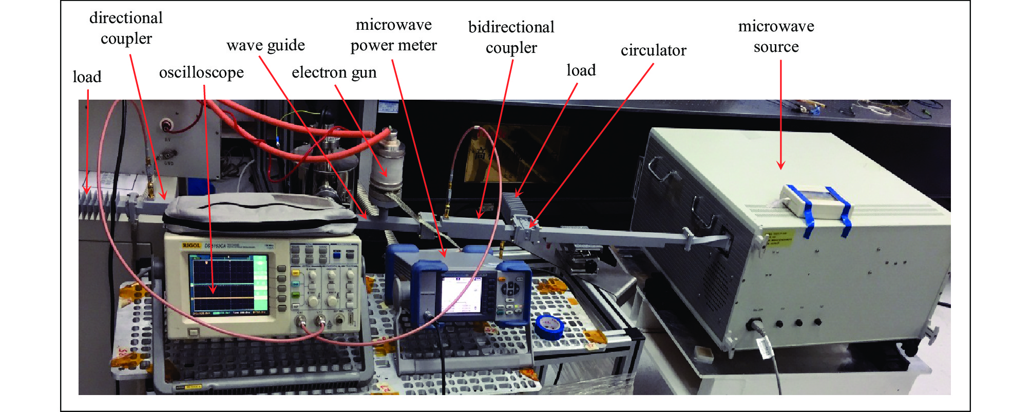
本实验利用电子束诱发大功率特殊波导微放电实验布局示意图如图2所示,通过设计特殊矩形压缩波导,在特殊矩形压缩波导两端设置密封窗,并在特殊矩形压缩波导上开微孔,利用真空系统对特殊矩形压缩波导抽真空,实验时在特殊矩形波导结构内通入大功率微波信号,当电子枪发射的电子束提供种子电子,诱发特殊压缩波导结构发生微放电,通过正反向波形检测法检测微放电现象,具体是利用双定向耦合器的正向耦合部分微波源输出的初始微波信号和定向耦合器耦合部分透射微波信号,初始微波信号和透射微波信号都分别经过衰减器和检波器输入示波器,同时双定向耦合器的反向耦合部分反射微波信号,反射微波信号经过衰减器和检波器输入功率计,通过示波器对比初始微波信号波形和透射微波信号波形,以及功率计监测反射微波信号的功率来判决是否发生微放电现象。
2.1 实验装置
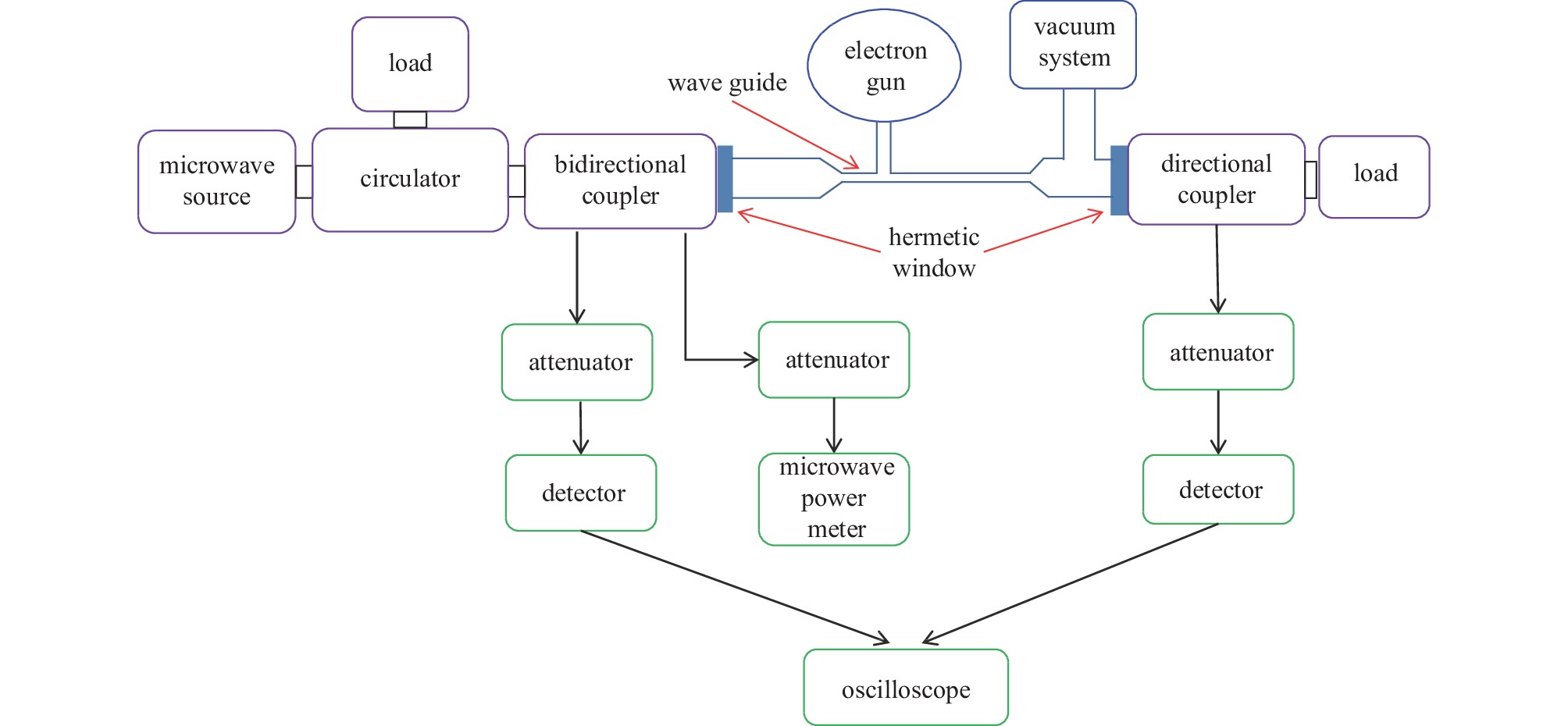
首先利用HFSS软件,设计实验专用X波段特殊矩形压缩波导,内径宽边a为22.86 mm,窄边b为1 mm,压缩段长54.5 mm,矩形波导压缩段的一侧宽边中心开ϕ5 mm孔,用于电子入射,矩形压缩波导两端对称线性延长放大,直至形成X波段BJ100标准波导(宽22.86 mm×窄10.16 mm),两侧放大段波导长度均为64 mm,在BJ100标准矩形波导一侧窄边中心开ϕ6 mm孔,用于抽真空,特殊矩形波导结构仿真模型如图3所示。所用电子枪为热阴极电子发射模式,电子枪提供电子束能量30 keV,流强30 mA,束斑大小为ϕ5 mm;大功率微波源性能参数如表1所示,真空系统采用机械泵和分子泵二级抽气。波导环形器,定向耦合器,衰减器和检波器均为X波段标准器件,环形器隔离度为20 dB,定向耦合器耦合度为30 dB,波导密封窗介质材料为聚四氟乙烯;衰减器为SHX公司SMA系列标准衰减器,平均功率阈值2 W,峰值功率阈值0.5 kW;检波器功率阈值20 mW;功率计为ROHDE&SCHWARZ,探测功率范围1 nW~100 mW;示波器采用1 GHz采样率的RIGOL DS 5152CA示波器。
表 1 大功率微波源性能参数Table 1. Parameters of high power microwave sourceoperating frequency/GHz frequency bandwidth/MHz peak output power /kW microwave pulse output width/μs duty cycle/% 9.7 100 10 1 0.1 2.2 实验步骤
第一步,利用矢量网络测试仪分别测试实验布局图中环形器、双定耦、特殊矩形压缩波导、波导密封窗和定向耦合器等微波器件的插损、耦合度和隔离度等参数。
第二步,利用各部件和仪器搭建如图2所示的实验链路,对特殊矩形压缩波导和电子枪先抽真空,待真空度稳定,打开微波源,利用示波器和功率计观测反射和透射波形及功率并记录。
第三步,打开电子枪,调节电子枪灯丝电压和加速电压,发射电子束,利用示波器和功率计观测反射和透射波形及功率计并记录实验数据,并与之前未发射电子束情况下反射和透射波形和功率进行对比,记录实验结果。
2.3 实验结果
利用各部件和仪器,按照图2所示搭建实验链路,示波器1通道和2通道分别连接双定向耦合器的正向耦合端和定向耦合器的耦合端,功率计连接双定向耦合器的反向耦合端,实验现场如图4所示,对特殊波导和电子枪先抽真空,真空度达到2.6×10⁻³ Pa,开始实验。
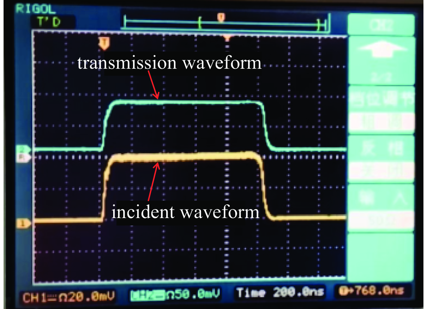
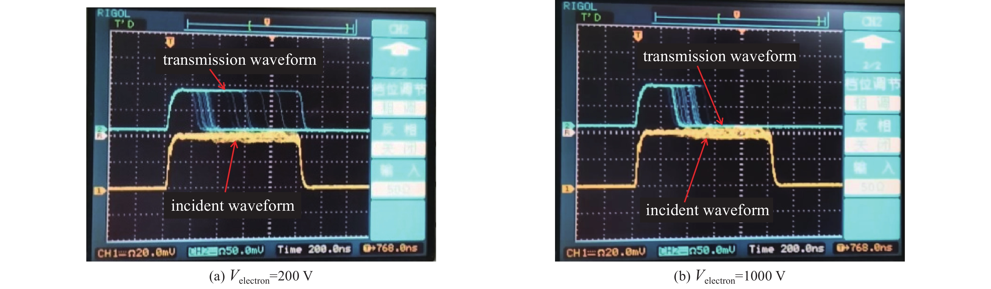
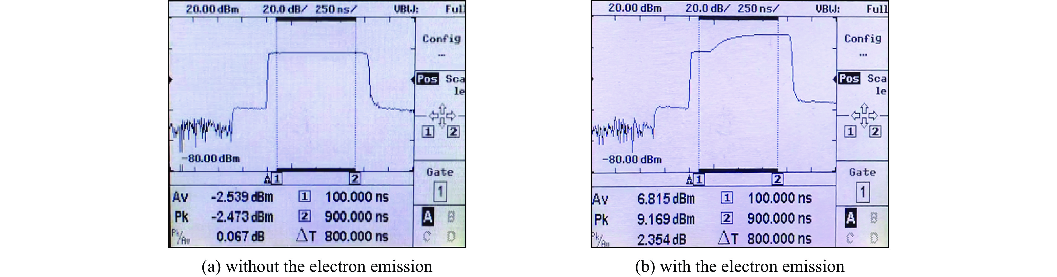
实验首先打开微波源,通入如表1设定的微波参数,观测透射和反射微波波形,传输波形如图5所示,图中蓝色波形为输出波形,黄色波形为输入波形,通过观察发现微波信号传输正常,透射波形和输入波形一致;之后打开电子枪,电子枪灯丝加7.7 V电压,当加速电压逐渐增大,达到200 V时,通过示波器观测到微波信号受到干扰,透射波形出现截止现象,如图6(a)所示。当增大电子枪加速电压,最大达1000 V时,透射微波信号截止明显提前,脉宽变窄,如图6(b)所示,此时观察电子枪灯丝的电流约为25 mA。同时通过功率计观测反射信号波形,观测结果如图7所示,可以看到当发生放电时,反射功率增大,最大增加幅度达10 dB。
 图 5 透射波形对比图Figure 5. Comparison of the transmission waveform and incident waveform without the electron emission
 图 6 透射波形对比图Figure 6. Comparison of the transmission and incident waveform with the electron emission
 图 7 反射波形放电前后对比图Figure 7. Comparison of the reflected waveform without or with the electron emission
通过透射波形和反射波形可以看到,当电子枪灯丝加载电压时,在加速电压作用下,出现严重的放电现象,透射波形脉冲宽度只有原来脉冲宽度的20%左右,反射功率增大约10 dB,说明电子枪提供的种子电子能够诱发特殊微波部件发生明显微放电现象。
3. 结 论
本文提出了一种利用电子枪提供空间电子作为种子电子开展微放电研究的实验方法,并对这一方法开展了实验验证。验证实验采用设计特殊矩形波导和X波段峰值功率10 kW的微波源,电子枪提供种子电子入射到特殊矩形压缩波导腔内,通过对比电子束入射特殊波导前后的透射和反射波形的方法。实验发现当电子枪提供的种子电子入射到特殊矩形波导腔内时,透射微波信号出现明显的截止现象,改变电子入射能量,观测到不同程度的微放电现象,入射电子能量越大,信号截止越早,反射功率增大,微放电现象越明显。实验证明了电子枪提供种子电子诱发微波器件发生微放电方法的可行性,该微放电效应实验方法为微波器件微放电机理研究提供了重要手段。
致 谢 衷心感谢中国空间技术研究院西安分院空间微波技术国家重点实验室对本工作给予的指导。
-
图 1 脉冲真空放电实验系统示意图
Figure 1. Schematic of experimental setup of the pulsed vacuum discharge system

图 3 放电现象侧视图
Figure 3. Side-view images of discharge phenomenon for an electrode structure

图 5 绝缘阳极电极的典型放电电压及阴极电流波形
Figure 5. Typical waveforms of discharge voltage and cathode current of the insulated anode structure


图 8 绝缘套筒直径为1 mm时的电极结构示意图及参数和电场分布图
Figure 8. When the insulating sleeve diameter is 1 mm, schematic of electrode structure and its parameters and electric field distribution[24]
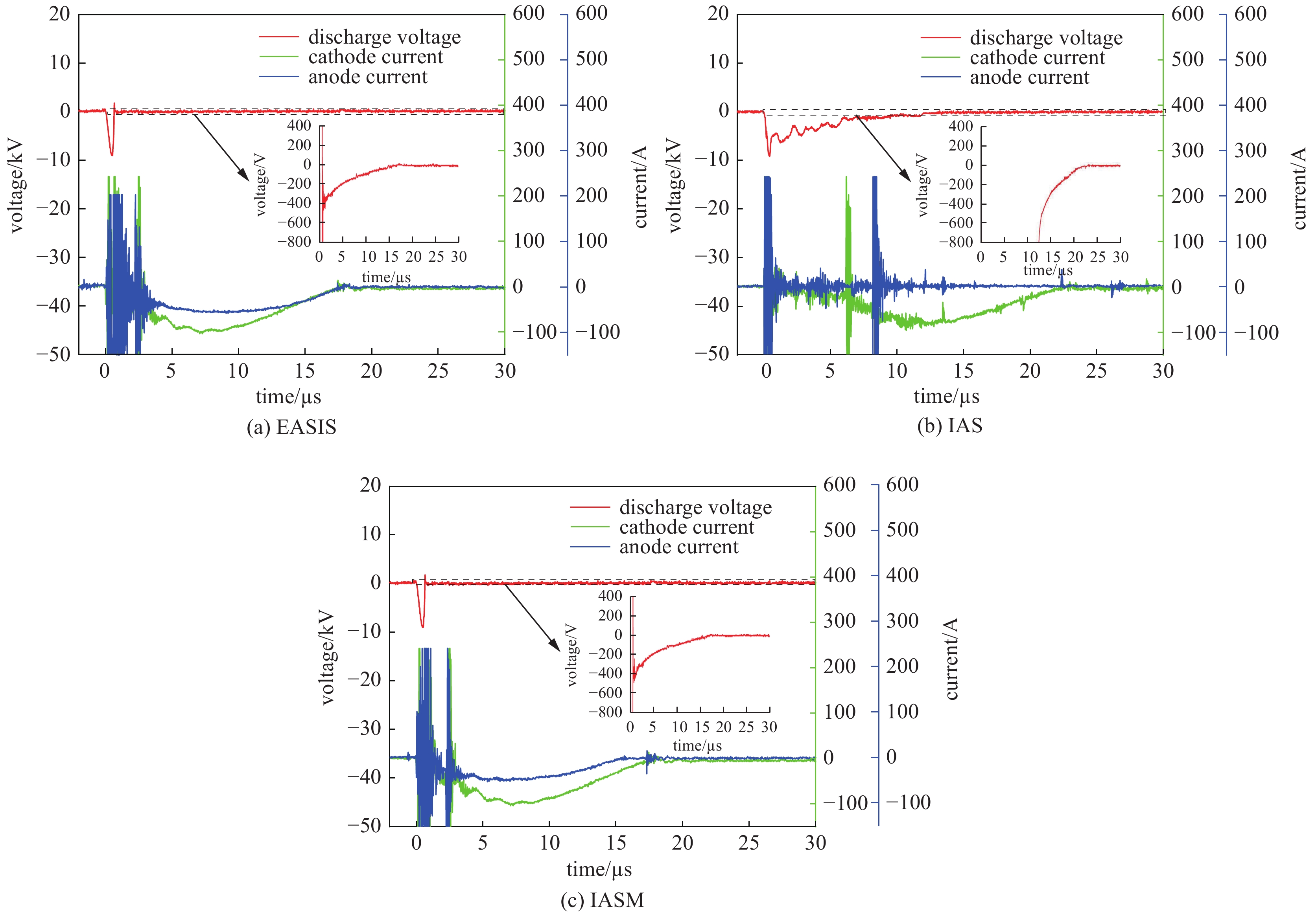


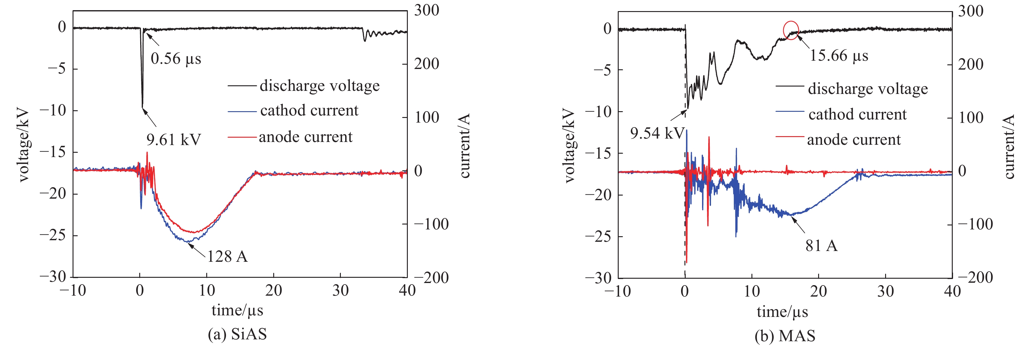
表 1 两种不同裸阳极电极结构的放电参数及等离子体生成
Table 1. Electrical parameters and plasma generation of two different exposed-anode electrode structures
electrode structure discharge voltage/kV cathode current/A anode current/A plasma density/(1016 m−3) propagation speed/(km·s−1) EAS 13 110 110 3.1 7.1 EASIS 10 130 90 14.5 8.2  下载: 导出CSV
表 2 带有不同阳极结构的电极的电参数[25]
Table 2. Electrical parameters of electrode with different anode structures[25]
electrode structure discharge voltage/kV cathode current/A anode current/A duration of cathode current/µs duration of anode current/µs EASIS 9 104 58 17.6 17.6 IAS 9 88 0 23 0 IASM 9 104 46 17.6 16
下载: 导出CSV
表 3 带有不同阳极结构的电极的等离子体参数[25]
Table 3. Plasma parameters of electrodes with different anode structures[25]
electrode structure plasma density/(1018 m−3) point of peak plasma density/(°) propagation speed/(km·s−1) plasma length/mm EASIS 2.94 0 8.5 5 IAS 9.70 0 9.6 4 IASM 16.40 15 11.1 9
下载: 导出CSV
W/mm discharge voltage/kV cathode current/A anode current/A duration of cathode current/µs duration of anode current/µs 0.2 9 104 23 17.6 9 1.0 9 104 46 17.6 16 3.0 9 104 50 17.6 17
下载: 导出CSV
W/mm plasma density/(1018 m−3) point of peak plasma density/(°) propagation speed/(km·s−1) plasma length/mm 0.2 37.3 15 33.2 16 1.0 16.4 15 11.1 9 3.0 11.3 15 9.3 6
下载: 导出CSV
表 6 相同阴极电流时不同电极结构的电参数及生成的等离子参数
Table 6. Electrical parameters and plasma parameters of different electrode structures at same cathode current
anode structure discharge voltage/kV cathode current/A anode current/A plasma density/(1016 m−3) CAS 15 250 250 2.95 SpAS 15 250 250 6.25
下载: 导出CSV
-
[1] Vondra R, Thomassen K, Solbes A. A pulsed electric thruster for satellite control[J]. Proceedings of the IEEE, 1971, 59(2): 271-277. doi: 10.1109/PROC.1971.8132 [2] Rayburn C D, Campbell M E, Mattick A T. Pulsed plasma thruster system for microsatellites[J]. Journal of Spacecraft and Rockets, 2005, 42(1): 161-170. doi: 10.2514/1.15422 [3] Frisbee R H. Advanced space propulsion for the 21st century[J]. Journal of Propulsion and Power, 2003, 19(6): 1129-1154. doi: 10.2514/2.6948 [4] Mazouffre S. Electric propulsion for satellites and spacecraft: established technologies and novel approaches[J]. Plasma Sources Science and Technology, 2016, 25: 033002. [5] Burton R L, Turchi P J. Pulsed plasma thruster[J]. Journal of Propulsion and Power, 1998, 14(5): 716-735. doi: 10.2514/2.5334 [6] Haque S E, Keidar M, Lee T. Low-thrust orbital maneuver analysis for cubesat spacecraft with a micro-cathode arc thruster subsystem[C]//Proceedings of 33rd International Electric Propulsion Conference. Washington, USA, 2013. [7] Coletti M, Ciaralli S, Gabriel S B. PPT development for nanosatellite applications: experimental results[J]. IEEE Transactions on Plasma Science, 2015, 43(1): 218-225. doi: 10.1109/TPS.2014.2368054 [8] 黄天坤, 武志文, 刘向阳, 等. 脉冲等离子体推力器电离机制数值分析[J]. 高电压技术, 2015, 41(9):2958-2964. (Huang Tiankun, Wu Zhiwen, Liu Xiangyang, et al. Numerical analysis on the ionization mechanism of pulsed plasma thrusters[J]. High Voltage Engineering, 2015, 41(9): 2958-2964 [9] Ling W Y L, Zhang Zhe, Tang Haibin, et al. In-plume acceleration of leading-edge ions from a pulsed plasma thruster[J]. Plasma Sources Science and Technology, 2018, 27: 104002. doi: 10.1088/1361-6595/aae19d [10] Schein J, Qi N, Binder R, et al. Inductive energy storage driven vacuum arc thruster[J]. Review of Scientific Instruments, 2002, 73(2): 925-927. doi: 10.1063/1.1428784 [11] 刘文正, 王浩. 同轴电极结构下真空放电等离子体生成及传播特性[J]. 强激光与粒子束, 2013, 25(8):2111-2116. (Liu Wenzheng, Wang Hao. Generation and propagation characteristics of vacuum discharge plasma with co-axial electrodes[J]. High Power Laser and Particle Beams, 2013, 25(8): 2111-2116 doi: 10.3788/HPLPB20132508.2111 [12] Keidar M, Zhuang Taisen, Shashurin A, et al. Electric propulsion for small satellites[J]. Plasma Physics and Controlled Fusion, 2015, 57: 014005. doi: 10.1088/0741-3335/57/1/014005 [13] Plyutto A A, Ryzhkov V N, Kapin A T. High speed plasma streams in vacuum arcs[J]. Soviet Physics Jetp, 1965, 20(2): 328-337. [14] Bolotov A, Kozyrev A, Korolev Y. A physical model of the low-current-density vacuum arc[J]. IEEE Transactions on Plasma Science, 1995, 23(6): 884-892. doi: 10.1109/27.476470 [15] Beilis I I. Modeling of a microscale short vacuum arc for a space propulsion thruster[J]. IEEE Transactions on Plasma Science, 2008, 36(5): 2163-2166. doi: 10.1109/TPS.2008.2004217 [16] Lukas J, Teel G, Kolbeck J, et al. High thrust-to-power ratio micro-cathode arc thruster[J]. AIP Advances, 2016, 6: 025311. doi: 10.1063/1.4942111 [17] 耿金越, 熊子昌, 龙军, 等. 微阴极电弧推力器研究进展[J]. 深空探测学报, 2017, 4(3):212-218, 231. (Geng Jinyue, Xiong Zichang, Long Jun, et al. The research progress in the micro-cathode arc thruster[J]. Journal of Deep Space Exploration, 2017, 4(3): 212-218, 231 [18] Polk J E, Sekerak M J, Ziemer J K, et al. A theoretical analysis of vacuum arc thruster and vacuum arc ion thruster performance[J]. IEEE Transactions on Plasma Science, 2008, 36(5): 2167-2179. doi: 10.1109/TPS.2008.2004374 [19] Neumann P R C, Bilek M M M, Tarrant R N, et al. A pulsed cathodic arc spacecraft propulsion system[J]. Plasma Sources Science and Technology, 2009, 18: 045005. doi: 10.1088/0963-0252/18/4/045005 [20] Krinberg I A. Three modes of vacuum arc plasma expansion in the absence and presence of a magnetic field[J]. IEEE Transactions on Plasma Science, 2005, 33(5): 1548-1552. doi: 10.1109/TPS.2005.856475 [21] Liu Wenzheng, Zhang Dejin, Kong Fei. The impact of electrode configuration on characteristics of vacuum discharge plasma[J]. Plasma Science and Technology, 2012, 14(2): 122-128. doi: 10.1088/1009-0630/14/2/08 [22] Liu Wenzheng, Wang Hao, Zhang Dejin. Impact of the electric field distribution on the generation characteristics of vacuum-arc discharge plasmas[J]. IEEE Transactions on Plasma Science, 2013, 41(7): 1690-1695. doi: 10.1109/TPS.2013.2262314 [23] Liu Wenzheng, Wang Hao, Dou Zhijun. Impact of the insulator on the electric field and generation characteristics of vacuum arc metal plasmas[J]. Plasma Science and Technology, 2014, 16(2): 134-141. doi: 10.1088/1009-0630/16/2/09 [24] Tian Jia, Liu Wenzheng, Cui Weisheng, et al. Generation characteristics of a metal ion plasma jet in vacuum discharge[J]. Plasma Science and Technology, 2018, 20: 085403. doi: 10.1088/2058-6272/aabedf [25] Tian Jia, Liu Wenzheng, Gao Yongjie, et al. Discharge and metallic plasma generation characteristics of an insulated anode with a micropore[J]. Physics of Plasmas, 2019, 26: 023511. doi: 10.1063/1.5078677 [26] 刘文正, 陈修阳, 崔伟胜, 等. 锥–螺旋电极在真空等离子体生成中的作用[J]. 高电压技术, 2017, 43(6):1863-1867. (Liu Wenzheng, Chen Xiuyang, Cui Weisheng, et al. Impact of cone-spiral electrode on generation characteristics of vacuum-arc discharge plasmas[J]. High Voltage Engineering, 2017, 43(6): 1863-1867 [27] Cui Wensheng, Liu Wenzheng, Gao Yongjie, et al. Discharge characterization of a multi-anode electrode geometry for vacuum arc thruster[J]. Plasma Sources Science and Technology, 2019, 28: 125010. doi: 10.1088/1361-6595/ab27d8 [28] Andruczyk D, Tarrant R N, James B W, et al. Langmuir probe study of a titanium pulsed filtered cathodic arc discharge[J]. Plasma Sources Science and Technology, 2006, 15(3): 533-537. doi: 10.1088/0963-0252/15/3/032 [29] Borthakur S, Talukdar N, Neog N K, et al. Study of plasma parameters in a pulsed plasma accelerator using triple Langmuir probe[J]. Physics of Plasmas, 2018, 25: 013532. doi: 10.1063/1.5009796 [30] Shao Jiahang, Antipov S P, Baryshev S V, et al. Observation of field-emission dependence on stored energy[J]. Physical Review Letters, 2015, 115: 264802. doi: 10.1103/PhysRevLett.115.264802 [31] Myers R M, Arrington L A, Pencil E J, et al. Pulsed plasma thruster contamination[C]//Proceedings of the 32nd Joint Propulsion Conference and Exhibit. Lake Buena Vista, 1996. 期刊类型引用(1)
1. 刘文正,姜希涛,田甲,张文俊,徐帅,於金亮. 具有内外分段阳极结构的金属离子等离子体推进器的放电特性. 高电压技术. 2023(01): 391-400 .  百度学术
百度学术其他类型引用(3)
-


 下载:
下载:


 点击查看大图
计量
- 文章访问数: 1643
- HTML全文浏览量: 598
- PDF下载量: 82
- 被引次数: 4
