Cold cavity characteristics of a new type of low-inductance magnetically insulated transmission line
-
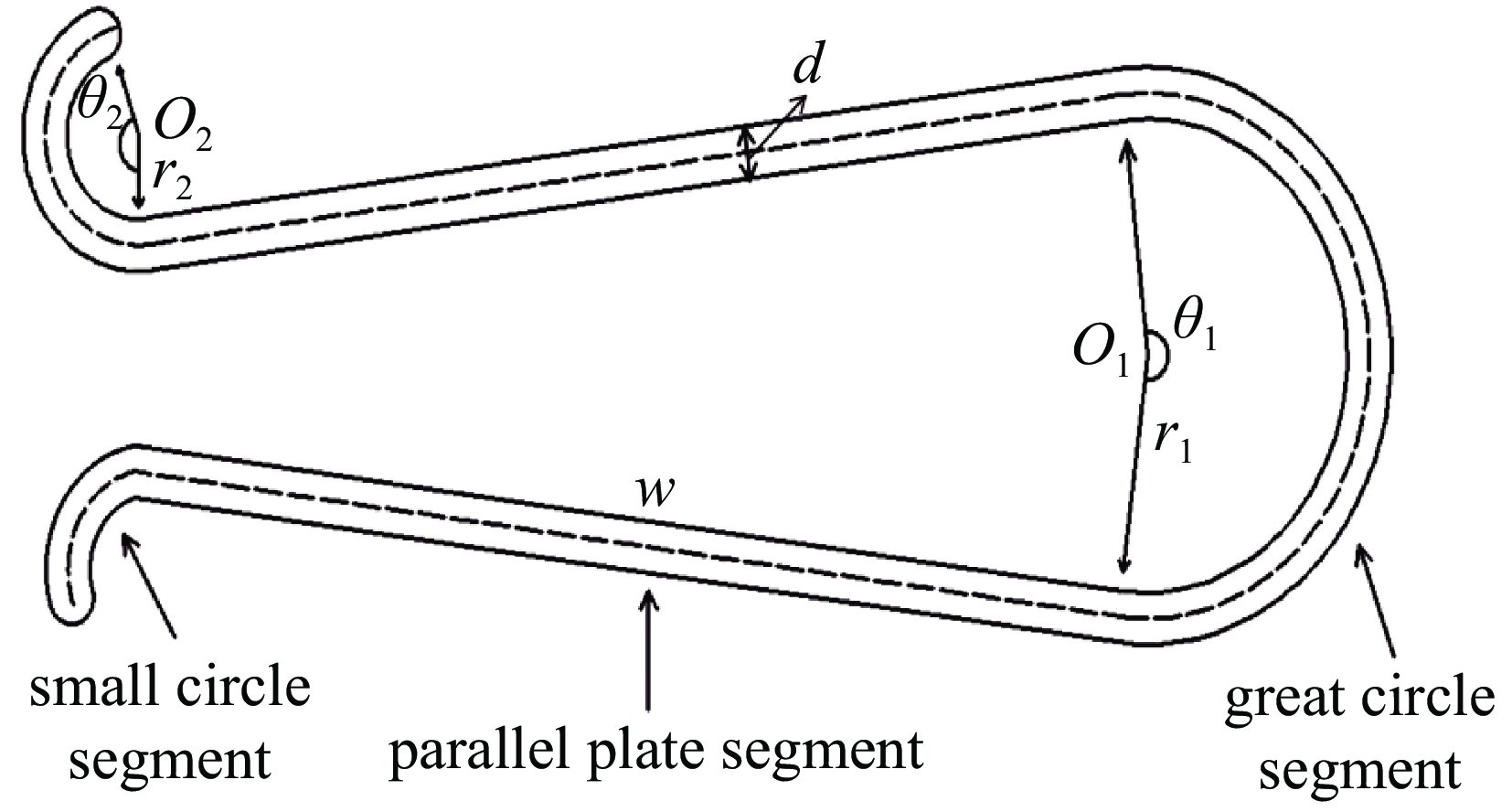
摘要: 研究了一种新型低电感花瓣形磁绝缘传输线的冷腔特性。该传输线构型的横向剖面的真空部分由12个类似花瓣形状的周期组成,而每个周期又由平行板和同轴圆弧两种基本传输线构型组成。该构型的整体轮廓有效增加了电极面积,使得传输线的电感大大降低,从而实现使用单层磁绝缘传输线即可获得较低的阻抗,规避了多层汇流结构带来的复杂的PHC结构和磁零位区损失问题。首先,分别计算出两种基本构型单元的电磁场分布、电感、电容和阻抗;而后,再整体计算分析出花瓣形磁绝缘传输线的电磁特性参数;同时,还通过数值模拟来分析该传输线的冷腔特性,获得了该传输线的阻抗值及电磁场分布,并将数值模拟结果与理论计算值进行了对比分析,结果验证了理论计算方法的正确性。Abstract: The vacuum part of the transverse section of this configuration is composed of 12 petal-like periods, and each period is composed of two basic transmission line configurations: parallel plates and coaxial arcs. The overall outline of this configuration effectively increases the electrode area, which greatly reduces the inductance of the transmission line, so that a lower impedance can be obtained by using a single-layer magnetically insulated transmission line,which avoids the complex PHC structure and the loss of the magnetic null region caused by the multi-layer bus structure. The electromagnetic field distribution, inductance, capacitance, and impedance of the two basic configuration units are calculated separately, and then the electromagnetic characteristic parameters of the petal-shaped magnetic insulated transmission line are calculated and analyzed as a whole. At the same time, the cold cavity characteristics of the transmission line are analyzed through numerical simulation, the impedance value and electromagnetic field distribution of the transmission line are obtained, and the numerical simulation results are compared with the theoretical calculation values for verification and analysis.
-
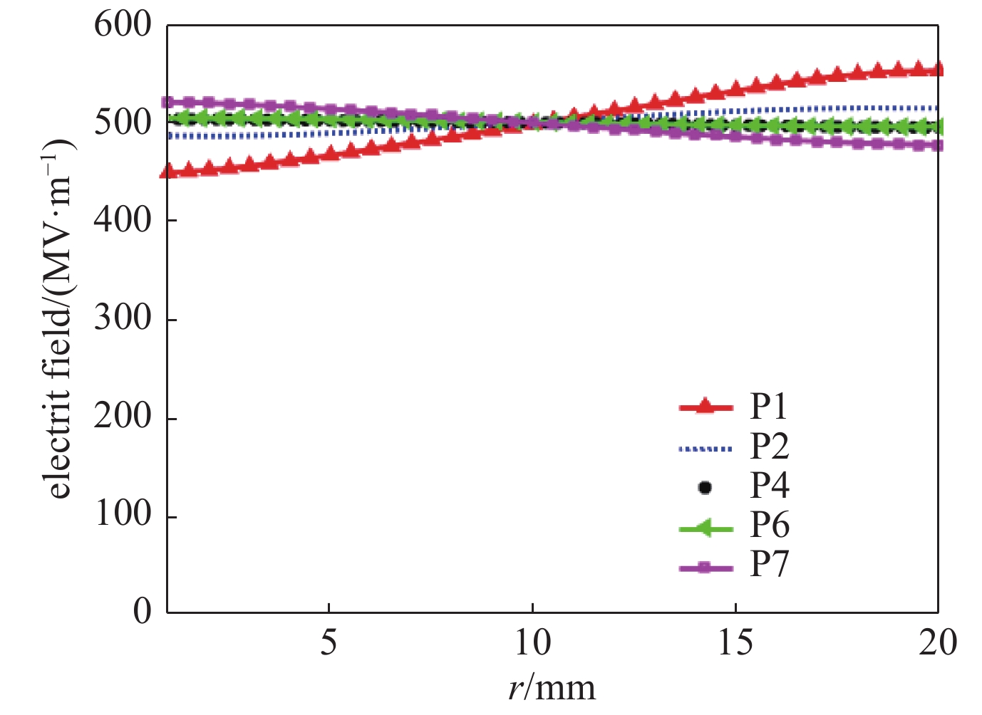
表 1 理论计算与Chipic模拟的点的电场分布对比
Table 1. Comparison of electric field distribution between theoretical calculation and Chipic simulation point
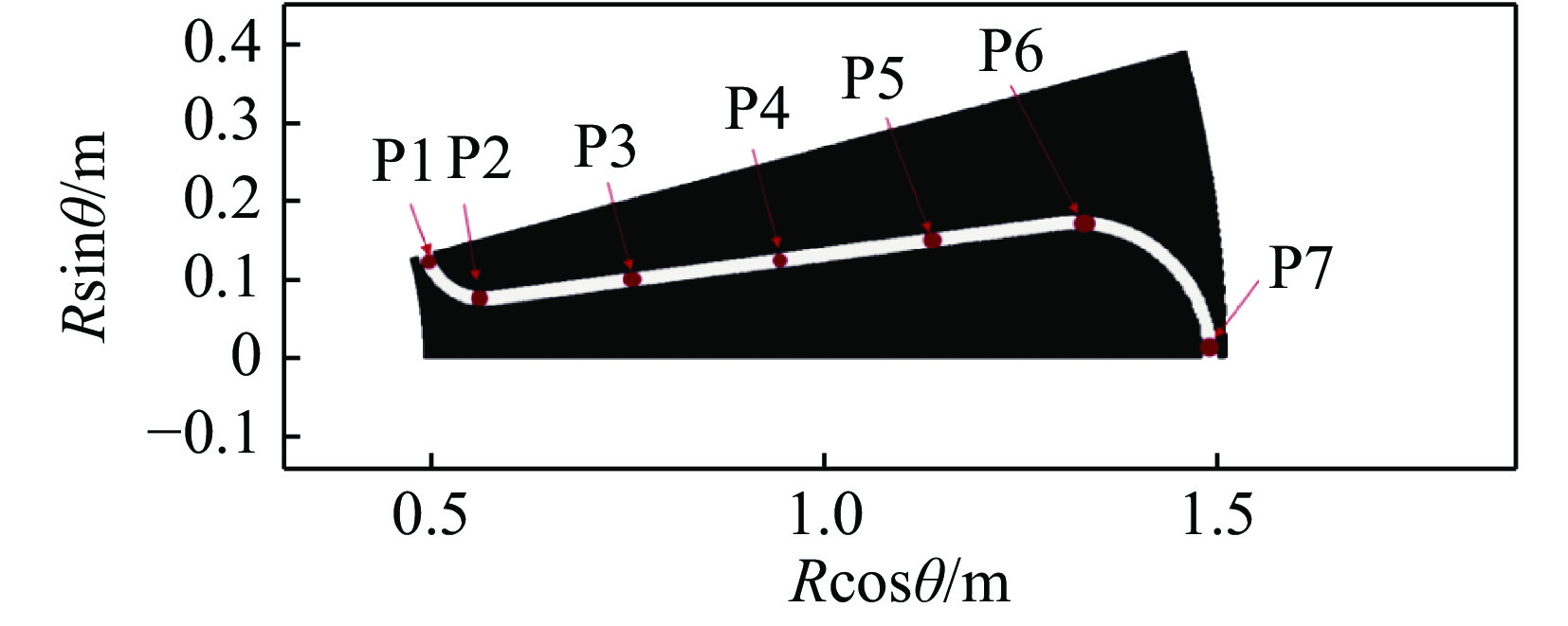
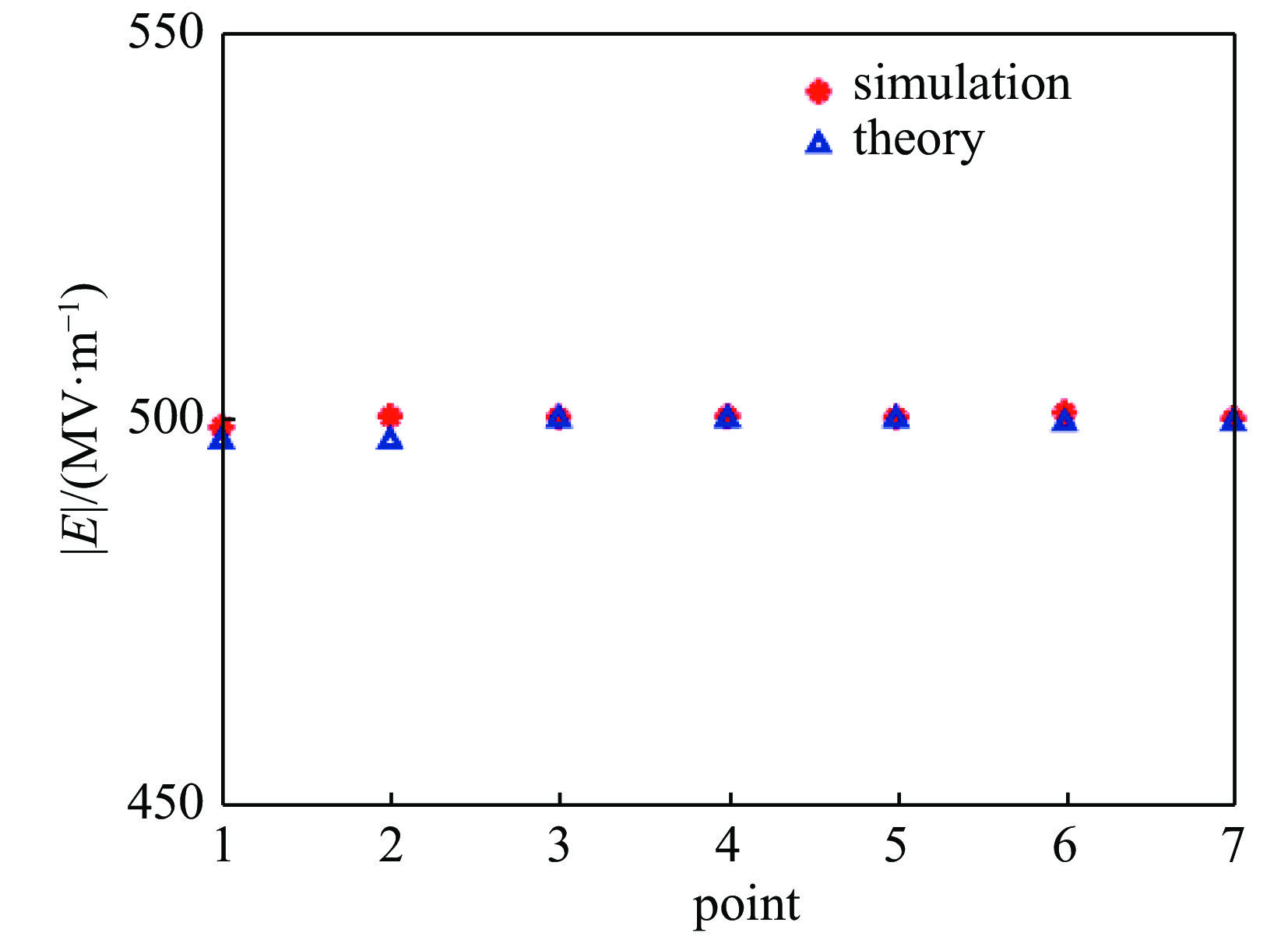
point theoretical calculation/(MV·m−1) chipic simulation/(MV·m−1) relative error/% small circle segment P1 497.2 499.0 0.3 P2 497.2 500.4 0.6 parallel plate segment P3 500.0 500.3 0.1 P4 500.0 500.4 0.1 P5 500.0 500.3 0.1 great circle segment P6 499.5 500.9 0.3 P7 499.5 500.9 0.1 表 2 理论计算与Chipic模拟的点的磁场分布对比
Table 2. Comparison of magnetic field distribution between theoretical calculation and Chipic simulation point
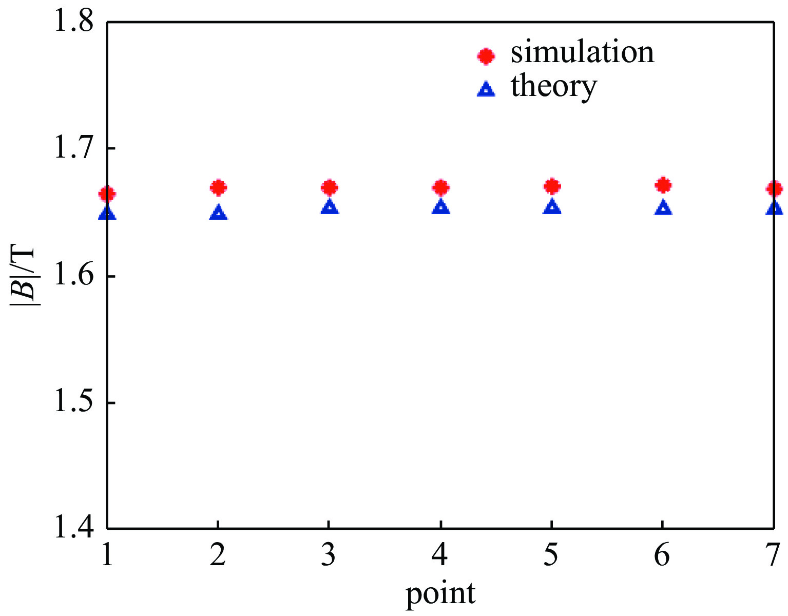
theoretical calculation/T chipic simulation/T relative error/% small circle segment P1 1.648 1.664 1.0 P2 1.648 1.669 1.3 parallel plate segment P3 1.653 1.669 1.0 P4 1.653 1.669 1.0 P5 1.653 1.670 1.0 great circle segment P6 1.652 1.671 1.2 P7 1.652 1.668 1.0 -
[1] Turchi P J, Baker W L. Generation of high-energy plasmas by electromagnetic implosion[J]. Journal of Applied Physics, 1973, 44(11): 4936-4945. [2] 赵小明. 磁化靶聚变等离子体电磁内爆压缩模拟研究[D]. 北京: 中国工程物理研究院, 2019: 5-7Zhao Xiaoming. Simulation on the compression of magnetized target fusion plasma by imploding solid liner[D]. Beijing: China Academy of Engineering Physics, 2019: 5-7 [3] Matsuka W, Lee H. Determining the temperature and density distributions from a Z-pinch radiation source[C]//11th IEEE International Pulsed Power Conference. 1997: 826-831. [4] 肖德龙, 戴自换, 孙顺凯, 等. Z箍缩动态黑腔驱动靶丸内爆动力学[J]. 物理学报, 2018, 67:025203. (Xiao Delong, Dai Zihuan, Sun Shunkai, et al. Numerical studies on dynamics of Z-pinch dynamic hohlraum driven target implosion[J]. Acta Physica Sinica, 2018, 67: 025203 doi: 10.7498/aps.67.20171640 [5] Asay J R, Hall C A, Knudson M D. Recent advances in high-pressure equation-of-state capabilities[R]. SAND2000-0849C, 2000. [6] 宋盛义. 圆盘锥磁绝缘传输系统电磁性能及结构力学理论计算[D]. 北京: 中国工程物理研究院, 2004: 7-10Song Shengyi. Calculation of electromagnetic performance and structural mechanics of the circular-conic magnetically insulated transmission line[D]. Beijing: China Academy of Engineering Physics, 2004: 7-10 [7] Spielman R B, Deeney C, Chandler G A, et al. PBFA Z: a 60-TW/5-MJ Z-pinch driver[J]. AIP Conference Proceedings, 1997, 409(1): 101-118. [8] Zhang Pengfei, Hu Yang, Yang Hailiang, et al. Experimental study on magnetically insulated transmission line electrode surface evolution process under MA/cm current density[J]. Physics of Plasmas, 2016, 23: 0133105. [9] Zou Wenkang, Wei Bing, Liu Laqun, et al. Coaxial-conical transition in magnetically insulated transmission line[J]. IEEE Transactions on Plasma Science, 2018, 46(6): 1913-1920. [10] 邹文康, 郭帆, 王贵林, 等. 聚龙一号装置磁绝缘传输线的电流损失特性[J]. 高电压技术, 2015, 41(6):1844-1851. (Zou Wenkang, Guo Fan, Wang Guilin, et al. Current loss properties of the magnetically insulated transmission line in the PTS facility[J]. High Voltage Engineering, 2015, 41(6): 1844-1851 [11] 毛重阳, 薛创, 肖德龙, 等. “聚龙一号”4层绝缘堆和真空区电路模拟方法[J]. 强激光与粒子束, 2020, 32:025004. (Mao Chongyang, Xue Chuang, Xiao Delong, et al. Simulation method of quadruple-level circuit model for stack and vacuum section of Julong-I facility[J]. High Power Laser and Particle Beams, 2020, 32: 025004 doi: 10.11884/HPLPB202032.190330 [12] Leopold J G, Navon I. Instabilities in the electron flow along magnetically insulated transmission lines[C]//2013 Abstracts IEEE International Conference on Plasma Science (ICOPS). 2013: 1. [13] Leopold J G, Gad R, Navon I. The flow dynamics along non-uniform self magnetically insulated transmission lines[C]//2011 IEEE Pulsed Power Conference. 2011: 856-860. [14] Madrid E A, Rose D V, Welch D R, et al. Steady-state modeling of current loss in a post-hole convolute driven by high power magnetically insulated transmission lines[J]. Physical Review Accelerators and Beams, 2013, 16: 120401. [15] 赵海龙, 董烨, 周海京, 等. 脉冲功率装置汇流区由电子发射导致的电流损失机制[J]. 强激光与粒子束, 2016, 28:015009. (Zhao Hailong, Dong Ye, Zhou Haijing, et al. Preliminary evaluation of current loss mechanism caused by electron emission at current convergence region on pulsed power facilities[J]. High Power Laser and Particle Beams, 2016, 28: 015009 doi: 10.11884/HPLPB201628.015009 [16] 周良骥, 邓建军, 蒋吉昊, 等. 一种磁绝缘汇集电流结构: 202020285042.5[P]. 2020-09-01Zhou Liangji, Deng Jianjun, Jiang Jihao, et al. Magnetic insulation current collection structure: 202020285042.5[P]. 2020-09-01 [17] 戴巍, 朱旭智, 刘腊群, 等. “聚龙一号”装置四层圆盘锥磁绝缘传输线的三维粒子模拟研究[J]. 现代电子技术, 2015, 38(3):144-148. (Dai Wei, Zhu Xuzhi, Liu Laqun, et al. Study on 3-D particle simulation of four-level coaxial circular-cone magnetically-insulated transmission line for “JuLong-1”[J]. Modern Electronics Technique, 2015, 38(3): 144-148 doi: 10.3969/j.issn.1004-373X.2015.03.044 -



 下载:
下载:
