

The self-ion irradiation effects in 6061-Al alloy
-
摘要: 铝合金是国内外研究堆的主要结构材料,在前期300#研究堆主要结构材料铝合金辐照性能研究的基础上,通过离子辐照研究6061-Al合金的微观结构损伤和引起的硬度变化,以开展较高辐照剂量下6061-Al合金损伤效应的前期探索。结果表明,经过自离子辐照后,6061-Al合金中产生了夹角为72°的位错环等缺陷,随着辐照剂量从0.218×1016 cm−2增加到4.367×1016 cm−2,缺陷密度明显增加,但选区电子衍射表明合金保持了很好的晶体结构,并没有发生非晶化。纳米压痕测试表明,不同辐照剂量下,样品中产生了不同程度的硬化,且微观硬度随着辐照剂量的增加而增加,当剂量增加到2.183×10¹⁶和4.367×1016 cm−2时,辐照硬化达到饱和,约为11%。研究结果可为初步预测较高中子辐照剂量下6061-Al合金结构和性能的变化提供数据支撑。Abstract: Aluminum alloy is the main structural material of research reactors at home and abroad. In this paper, on the basis of the research on the irradiation damage of the structural material aluminum alloy in the 300# research reactor, the microstructural damage and hardness change caused by ion irradiation in 6061-Al alloy are studied to carry out the early exploration of the damage effect of 6061-Al alloy under higher neutron irradiation doses. The results show that 1/3<111> dislocation loops with angles of 72° are generated in 6061-Al alloy after self-ion irradiation. The defect density increases obviously with the increasing irradiation dose from 0.218×1016 cm−2 to 4.367×1016 cm−2. However, the selected area electron diffraction shows a good lattice structure and no amorphous transformation occurs. Nano-indentation test demonstrates obvious irradiation hardening after irradiation and the microhardness increases with the increasing doses. At the highest damage dose of 2.183×1016 cm−2 and 4.367×1016 cm−2, the hardening reaches saturation, approaching 11%. These results can provide data support for the preliminary prediction of the structure and property change in 6061-Al alloy under high neutron irradiation dose.
-
Key words:
- 6061-Al alloy /
- ion irradiation /
- dislocation loop /
- irradiation hardening /
- defect
-
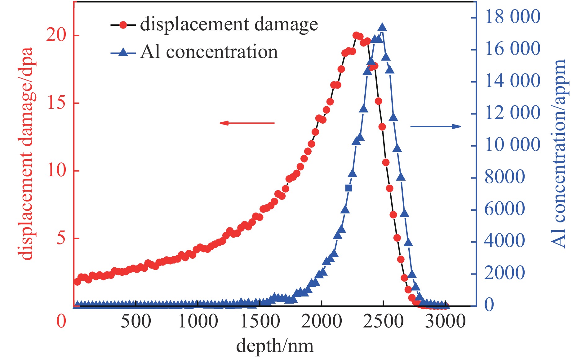
图 1 3 MeV Al离子辐照6061-Al合金的SRIM计算结果(以4.367×1016 cm−2剂量为例)
Figure 1. SRIM calculation result for 3 MeV Al ions in 6061-Al alloy normalized to an ion fluence of 4.367×1016 cm−2
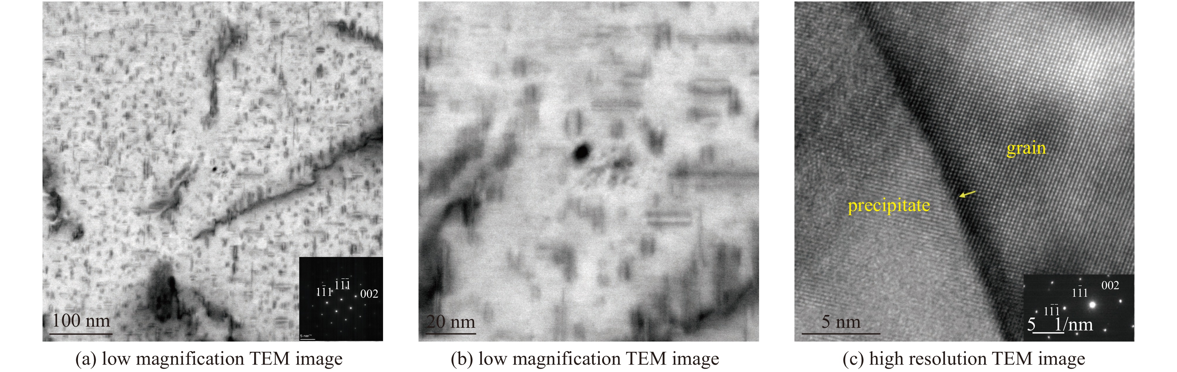
图 2 6061-Al合金中的析出物(均在[110]带轴下拍摄)
Figure 2. Precipitates in 6061-Al alloy (all the images are taken at [110] zone axis)

图 3 6061-Al合金中析出物的EDS能谱扫描结果
Figure 3. EDS spectrum of the precipitates in 6061-Al alloy

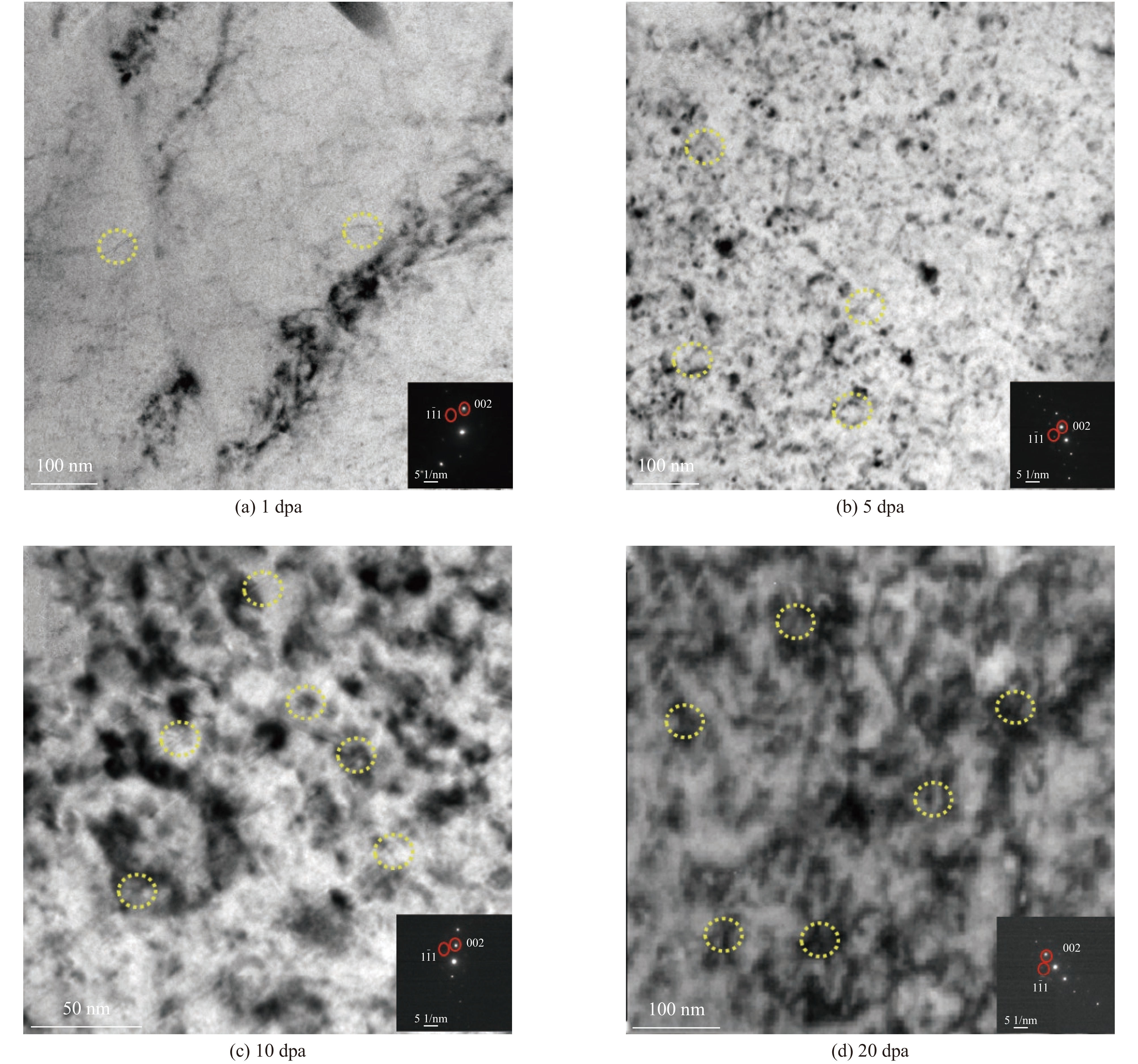
图 4 不同剂量离子辐照产生的损伤带
Figure 4. Damage zones induced by ion irradiation at different fluences
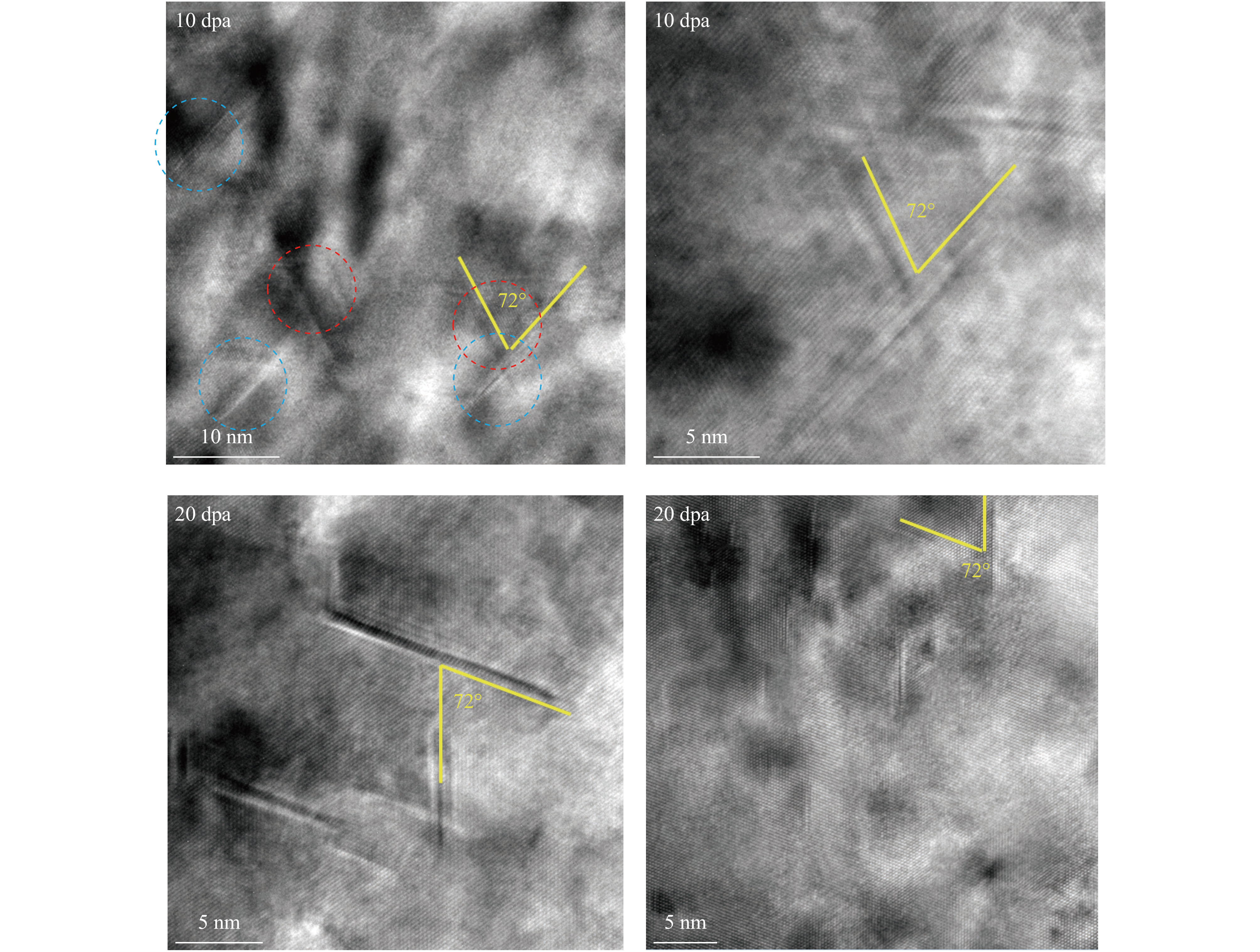
图 6 10,20 dpa下1/3<111>层错环的高分辨图像
Figure 6. HRTEM images of 1/3<111> faulted loops at 10 dpa and 20 dpa

图 7 离子辐照前后6061-Al合金硬度与压入深度变化曲线
Figure 7. Curves of hardness and indentation depth of 6061 Al alloy before and after ion irradiation
表 1 国产核级6061-Al合金的化学成分
Table 1. Chemical composition of nuclear-grade 6061-Al alloy
elements mass fraction/% Mg 0.80~1.20 Si 0.40~0.80 Cu 0.15~0.40 Cr 0.04~0.35 Fe ≤0.70 Mn ≤0.04 Ti ≤0.15 Zn ≤0.25 other impurity elements ≤0.05 Al balanced  下载: 导出CSV
-
[1] Garric V, Colas K, Donnadieu P, et al. Impact of the microstructure on the swelling of aluminum alloys: characterization and modelling bases[J]. Journal of Nuclear Materials, 2021, 557: 153273. doi: 10.1016/j.jnucmat.2021.153273 [2] Soria S R, Tolley A, Sánchez E A. The influence of microstructure on blistering and bubble formation by He ion irradiation in Al alloys[J]. Journal of Nuclear Materials, 2015, 467: 357-367. doi: 10.1016/j.jnucmat.2015.09.051 [3] 郁金南. 材料辐照效应[M]. 北京: 化学工业出版社, 2007Yu Jinnan. Radiation effects in materials[M]. Beijing: Chemical Industry Press, 2007 [4] Sturcken E F. Irradiation effects in magnesium and aluminum alloys[J]. Journal of Nuclear Materials, 1979, 82(1): 39-53. doi: 10.1016/0022-3115(79)90037-0 [5] King R T, Jostsons A. Irradiation damage in a 2.2 pct magnesium-aluminum alloy[J]. Metallurgical Transactions A, 1975, 6(4): 863-868. doi: 10.1007/BF02672309 [6] Kamigaki N, Furuno S, Hojou K, et al. Evolution of structural damage in aluminum alloys irradiated with helium ions[J]. Journal of Nuclear Materials, 1992, 191/194: 1214-1218. doi: 10.1016/0022-3115(92)90667-A [7] Was G S. Challenges to the use of ion irradiation for emulating reactor irradiation[J]. Journal of Materials Research, 2015, 30(9): 1158-1182. doi: 10.1557/jmr.2015.73 [8] Jiao Z, Michalicka J, Was G S. Self-ion emulation of high dose neutron irradiated microstructure in stainless steels[J]. Journal of Nuclear Materials, 2018, 501: 312-318. doi: 10.1016/j.jnucmat.2018.01.054 [9] Pareige C, Kuksenko V, Pareige P. Behaviour of P, Si, Ni impurities and Cr in self ion irradiated Fe–Cr alloys – Comparison to neutron irradiation[J]. Journal of Nuclear Materials, 2015, 456: 471-476. doi: 10.1016/j.jnucmat.2014.10.024 [10] Was G S, Jiao Z, Getto E, et al. Emulation of reactor irradiation damage using ion beams[J]. Scripta Materialia, 2014, 88: 33-36. doi: 10.1016/j.scriptamat.2014.06.003 [11] Zinkle S J, Snead L L. Opportunities and limitations for ion beams in radiation effects studies: bridging critical gaps between charged particle and neutron irradiations[J]. Scripta Materialia, 2018, 143: 154-160. doi: 10.1016/j.scriptamat.2017.06.041 [12] Stoller R E, Toloczko M B, Was G S, et al. On the use of SRIM for computing radiation damage exposure[J]. Nuclear Instruments and Methods in Physics Research Section B: Beam Interactions with Materials and Atoms, 2013, 310: 75-80. [13] Oliver W C, Pharr G M. An improved technique for determining hardness and elastic modulus using load and displacement sensing indentation experiments[J]. Journal of Materials Research, 1992, 7(6): 1564-1583. doi: 10.1557/JMR.1992.1564 [14] Oliver W C, Pharr G M. Measurement of hardness and elastic modulus by instrumented indentation: advances in understanding and refinements to methodology[J]. Journal of Materials Research, 2004, 19(1): 3-20. doi: 10.1557/jmr.2004.19.1.3 [15] Li Xiaodong, Bhushan B. A review of nanoindentation continuous stiffness measurement technique and its applications[J]. Materials Characterization, 2002, 48(1): 11-36. doi: 10.1016/S1044-5803(02)00192-4 [16] Liu Xiangbing, Wang Rongshan, Ren Ai, et al. Evaluation of radiation hardening in ion-irradiated Fe based alloys by nanoindentation[J]. Journal of Nuclear Materials, 2014, 444(1/3): 1-6. [17] 王广厚. 粒子同固体相互作用物理学[M]. 北京: 科学出版社, 1991Wang Guanghou. Particle-solid interaction physics[M]. Beijing: Science Press, 1991 [18] Osetsky Y N, Bacon D J, Serra A, et al. Stability and mobility of defect clusters and dislocation loops in metals[J]. Journal of Nuclear Materials, 2000, 276(1/3): 65-77. [19] Singh B N, Foreman A J E, Trinkaus H. Radiation hardening revisited: role of intracascade clustering[J]. Journal of Nuclear Materials, 1997, 249(2/3): 103-115. [20] 郭立平, 罗凤风, 于雁霞. 核材料辐照位错环[M]. 北京: 国防工业出版社, 2017Guo Liping, Luo Fengfeng, Yu Yanxia. Dislocation loops in irradiated nuclear materials[M]. Beijing: National Defense Industry Press, 2017 [21] Changizian P, Zhang H K, Yao Z. Effect of simultaneous helium implantation on the microstructure evolution of Inconel X-750 superalloy during dual-beam irradiation[J]. Philosophical Magazine, 2015, 95(35): 3933-3949. doi: 10.1080/14786435.2015.1109152 [22] Tartour J P, Washburn J. Climb kinetics of dislocation loops in aluminium[J]. The Philosophical Magazine:A Journal of Theoretical Experimental and Applied Physics, 1968, 18(156): 1257-1267. doi: 10.1080/14786436808227755 [23] Yang Tengfei, Guo Wei, Poplawsky J D, et al. Structural damage and phase stability of Al0.3CoCrFeNi high entropy alloy under high temperature ion irradiation[J]. Acta Materialia, 2020, 188: 1-15. doi: 10.1016/j.actamat.2020.01.060 [24] Lu Chenyang, Yang Taini, Jin Ke, et al. Radiation-induced segregation on defect clusters in single-phase concentrated solid-solution alloys[J]. Acta Materialia, 2017, 127: 98-107. doi: 10.1016/j.actamat.2017.01.019 [25] Xiu Pengyuan, Bei Hongbin, Zhang Yanwen, et al. STEM characterization of dislocation loops in irradiated FCC alloys[J]. Journal of Nuclear Materials, 2021, 544: 152658. doi: 10.1016/j.jnucmat.2020.152658 [26] Murakami S, Miyazaki A, Mizuno M. Modeling of irradiation embrittlement of reactor pressure vessel steels[J]. Journal of Engineering Materials and Technology, 2000, 122(1): 60-66. doi: 10.1115/1.482766 [27] Yamamoto T, Odette G R, Kishimoto H, et al. On the effects of irradiation and helium on the yield stress changes and hardening and non-hardening embrittlement of ~8Cr tempered martensitic steels: compilation and analysis of existing data[J]. Journal of Nuclear Materials, 2006, 356(1/3): 27-49. [28] Pharr G M, Herbert E G, Gao Y F. The indentation size effect: a critical examination of experimental observations and mechanistic interpretations[J]. Annual Review of Materials Research, 2010, 40: 271-292. doi: 10.1146/annurev-matsci-070909-104456 [29] Wei Y P, Liu P P, Zhu Y M, et al. Evaluation of irradiation hardening and microstructure evolution under the synergistic interaction of He and subsequent Fe ions irradiation in CLAM steel[J]. Journal of Alloys and Compounds, 2016, 676: 481-488. doi: 10.1016/j.jallcom.2016.03.167 [30] Konings R J M, Allen T R, Stoller R E, et al. Comprehensive nuclear materials[M]. Amsterdam: Elsevier Science, 2012. [31] Huang H F, Li D H, Li J J, et al. Nanostructure variations and their effects on mechanical strength of Ni-17Mo-7Cr alloy under xenon ion irradiation[J]. Materials Transactions, 2014, 55(8): 1243-1247. doi: 10.2320/matertrans.M2014075 [32] Heintze C, Bergner F, Hernández-Mayoral M. Ion-irradiation-induced damage in Fe-Cr alloys characterized by nanoindentation[J]. Journal of Nuclear Materials, 2011, 417(1/3): 980-983. -

 点击查看大图
计量
- 文章访问数: 1044
- HTML全文浏览量: 454
- PDF下载量: 78
- 被引次数: 0
