

Modeling and simulation of halo effect of night vision system
-
摘要: 研究了微光夜视系统输出图像中光晕尺寸和灰度分布与系统参数之间的关系,建立了系统光晕效应的定量化表征模型。首先分析了系统输出图像中光晕的产生机理;其次依据微光夜视系统成像原理,通过分析光电阴极产生的光电子数及初角度分布、光电子在光电阴极与微通道板之间的运动、光电子与微通道板非开口壁碰撞后的运动规律及微光成像系统各环节对能量的逐级传递,研究了光晕的定量化表征方法;结合上述理论研究,建立了光晕的数字仿真模型。结果表明:所提出的光晕效应表征模型能够与实验结果中光晕的灰度分布及尺寸较好地吻合;随着强光源能量增大,系统光晕效应越明显,光晕效应对系统成像质量影响越大。Abstract: The relationship between the size and gray distribution of the halo in the output image of LLL(low light level) TV system and the parameters of the system was studied and a feature quantitative model of the halo was established. Firstly, the mechanism of the halo in the output image of the system was analyzed; Then, according to imaging theory, the feature quantitative method of the halo was realized by analyzing the number and the initial angular distribution of photoelectrons generated by photocathode, the movement of the photoelectrons between the photocathode and the MCP, and the collision law of the photoelectrons with non-opening wall of the MCP. Finally, the digital simulation model of the halo was built on the basis of the theories mentioned above. The experimental results show that: the results of the proposed halo effect model agree well that of experiment in gray distribution and size; the halo effect will be more obvious with the stronger of the light energy, which will generate greater impact on the imaging quality.
-
Key words:
- night vision system /
- halo effect /
- imaging theory /
- gray distribution /
- digital simulation
-
New parametric current transformers (NPCTs) are widely used to measure beam current in accelerators. Two "In-air-175" NPCTs from Bergoz Instrumentation[1] are selected for BEPCⅡelectron and positron ring. Current sensors are located on a vacuum chamber which has a ceramic break for avoiding the wall current from passing through[2]. The ceramic gap works as a capacity and determines the cutoff frequency. The positron NPCT will heat in the collider mode when the beam current is beyond 500 mA. To solve this problem, a series of studies and researches have been done.
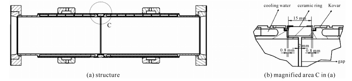
1. Mechanical structure of NPCT vacuum chamber
As the primary study indicates, the heating is quite relevant to the mechanical structure of NPCT. The BEPCⅡ NPCT vacuum chamber profile is shown in Fig. 1. The components of the NPCT vacuum chamber structure are listed in Table 1. An interlayer of water has been designed for cooling, the inlet and outlet of water near the flange side are not shown in Fig. 1. Kovar rings are used to seal the ceramic and the steel chamber. Two extend slices are made to avoid discharge and to protect the ceramic ring and the welding edge.
 Figure 1. NPCT vacuum chamber structureTable 1. Vacuum chamber parameters
component material data pipe steel 316 inner diameter: 96 mm, outer diameter: 111 mm water interlayer water thickness: 2 mm ceramic gap 95%Al2O3 width: 15 mm seal ring Kovar \\ | Show Table DownLoad:
CSV
DownLoad:
CSV
2. Heating problem and solutions
The positron ring NPCT's heating problem arose in 2013 when BEPCⅡ ran at high current collider mode. There were six PT100 temperature sensors: one was on the NPCT sensor, one was on the vacuum chamber, and the other four were on the water cooling pipe, the cooling water was about 16-20 ℃. When the single bunch current reached 10 mA, the temperature of sensor was over 60℃ and the vacuum chamber was near 50 ℃. In the meantime the water outlet temperature showed insufficient cooling. As the current would go up for getting higher luminosity, heating might become serious and destroy the sensor toroid. There are two reasonable explanations of the heating source: one is the power loss caused by wakefield effect of the discontinuous ceramic break[3], the other is the eddy current loss and the hysteresis loss of high frequency signal in the sensor. Methods have been taken to analyse and solve the problem since then.
2.1 Calculation of power loss of the gap structure
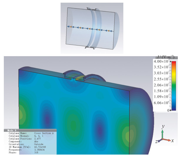
To verify the heating brought by the beam in the gap, a simulation based on CST has been done. As the ceramic gap and the vacuum chamber make a small cavity in a resonator, when charged particles are passing through, they lose energy due to the structure. To calculate the power loss, the loss factor is needed, which can be calculated in CST Particle Studio. A simplified vacuum model inside the chamber is established in CST as shown in Fig. 2. According to BEPCⅡ collider mode, particle sigma is 15 mm, commissioning energy is 1.89 GeV, beta is 0.999 9, and particle path is set in the central of the model. The boundary is set as PEC (perfect electronic conduct). The simulation result shows the loss factor of the structure is 11.2 V/nC.
 Figure 2. CST vacuum model and field distribution of simulation
As the loss factor means voltage loss per charge for a structure, the whole loss power is calculated as[3-4]
Ploss=IQKloss=I2tKlossN (1) where I is mean beam current, N is bunch number, t is revolution time, Kloss is loss factor. For the case I=600 mA, N=72, t=7.9 ns and Kloss=11.2 V/nC, Ploss is about 44 W.
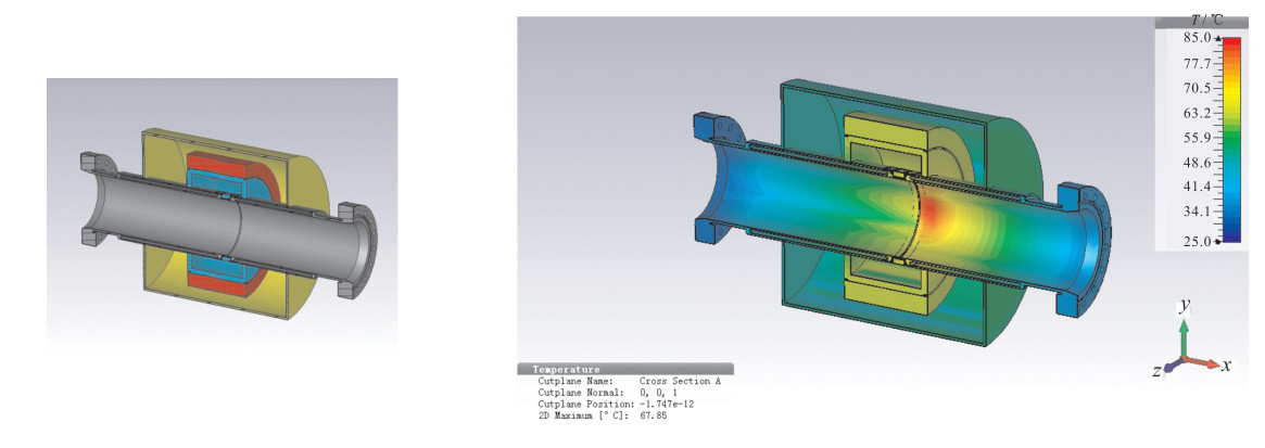
For getting the distribution of the modes, CST Microwave Studio is used to do the TM Eigen mode simulation with frequency up to 15 GHz. The highest field amplitude near the gap is 4×10⁷ V/m at 3.35 GHz as shown in Fig. 2. A complete model includes vacuum chamber, sensor toroid, support and shield is established for post-processing to calculate the temperature. An extreme condition is set that all the power is used for thermal analysis. The material of the shield is copper and the support is Bakelite. In the simulation only natural heat dissipation is included, water cooling is not considered for getting the actual static value, the highest temperature in the chamber is 80 ℃ near the gap. The model and simulation results are shown in Fig. 3.
 Figure 3. NPCT model and static temperature distribution in CST
This simulation only indicates power loss inside the gap, it proves that the structure contributes part of the heating and extra cooling is necessary. The results of the simulation could be a guide for further vacuum chamber design. Making the gap simple and smaller could reduce the loss factor but lead to the reduction of the gap capacity, which will cause the sensor heating problem.
2.2 Sensor heating analysis and solution
Besides the heating on the pipe, the sensor temperature rises, which is a more critical problem to settle. An "S-shaped" copper pipe is designed to wind out of the sensor for cooling water to pass through, but the effect is not obvious, so a fundamental solution is needed.
The NPCT sensor uses finemet cores made of high permeability amorphous alloy thin ribbons [1]. For magnetic materials there is a definition for power loss. Ph is hysteresis loss power, Pe is eddy current loss power, and the loss of the core can be calculated as[5]
W=Wh+We+Wr (2) in which
Wh=f∮HdM (3) We=af2t2Bmax2/ρ (4) and Wr is a loss related to the atomic structure of material, which can be ignored. In equations (3) and (4), f is signal frequency, M is intensity of magnetization, t is core material thickness (which is a constant in our case), Bmax is peak magnetic intensity, a is a constant coefficient, ρ is resistivity of the core. The iron loss of ferromagnetic materials and ferrite is related to frequency (f), f is the key parameter[5].
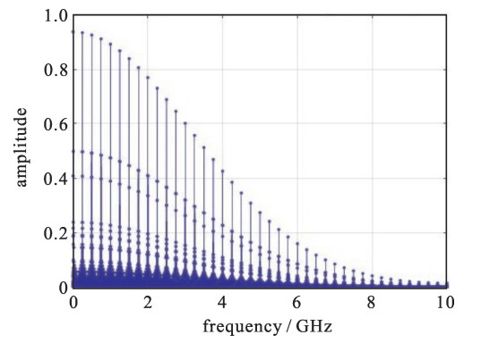
A spectrum of beam for collision mode of BEPCⅡ is simulated in Matlab, with 4 series of 18 bunches in 8 circles. For electron and positron rings with the same bunch mode, they share the same spectrum distribution. As it shows in Fig. 4, the most of the beam power is below 6 GHz. The NPCT bandwidth is DC-10 kHz [1], the higher frequency signal won't be responded and may cause the heating loss.
 Figure 4. Beam spectrum in collision mode
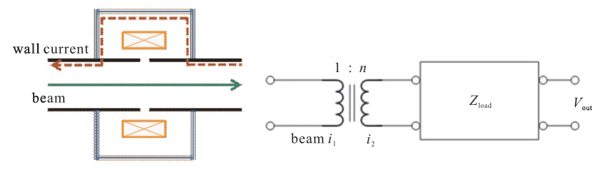
According to the NPCT sensor measurement principle, the mirror current flowing on the vacuum pipe is cut by a ceramic gap. The ceramic gap works like a capacitor, the high frequency of the mirror current passes through the gap, while the low frequency part flows along the outer shielding. The sensor "sees" that Ilow, f=Ibeam-Ihigh, f (I represents beam current, the character "f" in the subscript represents "frequency").
The whole NPCT sensor and front electronics is simplified as an equivalent circuit which is shown in Fig. 5. A transformer theory has been applied in the calculation. The beam current considered is the one turn primary current i1, i2 is the current in the secondary coil (the winding of the output). The electronics and other load are considered as an integrated impedance Zload, so the current reflected impedance Zref can be calculated as in equation (7)[6]
i1=ni2=nVoutZload (5) Zload=nVouti1=nSsensitivity (6) Zref=(1n)2Zload=nSsensitivityn2=Ssensitivityn=0.025Ω (7)  Figure 5. NPCT measurement principle and equivalent circuit
The sensitivity Ssensitivity of NPCT is 5 V/A in BEPCⅡ. The turns ratio n is 200 in 5 V/A range.
The -3 dB point of cutoff frequency is obtained when the impedance of the cavity Zcavity is equal to the impedance of the gap Zgap, the impedance of the wall conduct can be neglected when compare to the transformer reflected impedance Zref, so Zcavity≈Zref[1]. As Z=1/(2π fcuttoffC), the value C of the gap capacitance determines the higher cutoff frequency fcuttoff of the wall current entering into the cavity. Increase C will reduce fcuttoff at certain impedance, which also means reducing the high frequency signal flow through the sensor.
C of the ceramic gap can be approximately calculated as[7]
C=Sε0εcLc=π(r2out−r2in)ε0εcLc≈19pF (8) where the dielectric constant ε0=8.854×10⁻¹², the relative dielectric constant of ceramic εc=9[8], the ceramic ring effective insulation length Lc=10 mm, the outer radius of the ceramic rout=55.5 mm, the inner radius of the ceramic rin=48 mm.
When C is 19 pF, the fcuttoff is over 10 GHz which equals that Ihighf is all over 10 GHz, so Ilowf covers the whole bandwidth of the beam current. Most of the unwanted high frequency signal is "seen" by the sensor and causes the heating.
There are many methods to increase the capacitor, a simple way which does not need to break the vacuum chamber is: put a big parallel capacitor across the ceramic gap, they form a bigger capacitor Cadd. Cadd can be calculated as
Cadd=Sε0εkh=πdLkε0εkh≈8nF (9) where the area of the kapton foil S=27 883.2 mm2, the outer diameter of the vacuum d=111 mm, the length of the kapton foil Lk=80 mm, the thickness of the kapton foil h=110 μm, the relative dielectric constant of kapton foil εk=3.4[9].
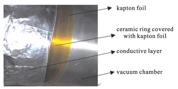
Cadd is parallelly connected with Cceramic, which is small enough to be ignored, fcutoff=1/(2πCZref) deceases to 800 MHz. The high frequency signal which can be seen by the sensor is reduced. In our case, a conductive layer with 110 μm-thick kapton foil is used to wind on the pipe, as shown in Fig. 6. The kapton foil wraps the ceramic, while the conductive layer is partly covered by the kapton foil with only one side stick to the vacuum chamber.
 Figure 6. Kapton foil and conductive layer
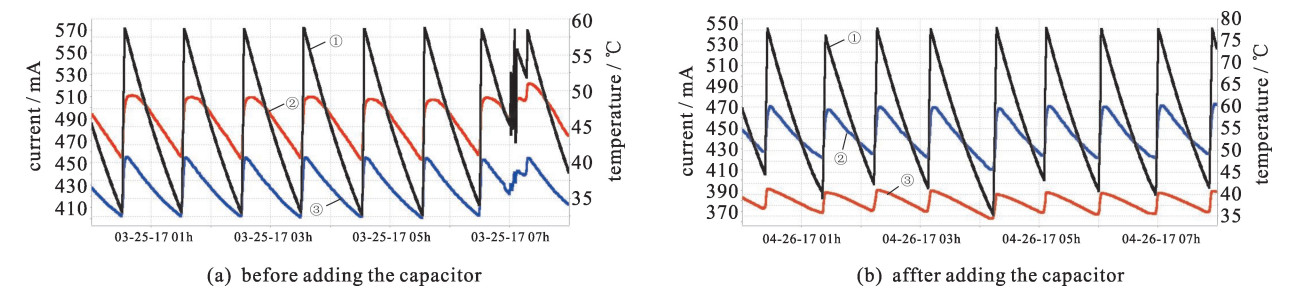
The temperature of the sensor indicates that the method is effective. Before adding capacitor to the gap, temperature of the sensor is much higher than the vacuum chamber. As the history data shown in Fig. 7, sensor temperature is about 50 ℃ (Fig. 7(a)), vacuum chamber temperature is about 40 ℃ (Fig. 7(a)) at 550 mA (peak current in Fig. 7(a)). After adding the capacitor to the gap, temperature of the sensor drops to 40 ℃ (Fig. 7(b)) at 550 mA (peak current in Fig. 7(b)), and the vacuum chamber temperature is 60 ℃ (Fig. 7(b)). Most power has been hold in the chamber for energy conservation. Note that the beam has the same pattern in this operation cycle.
 Figure 7. Beam current(①), sensor temperature(②), chamber temperature(③) before and after adding the capacitor
Definitely, the temperature change contains the above two contributions. Accurate calculation of power transfer needs more considerations.
3. Conclusion and discussion
The heating problem of current transformer (CT) is common in the accelerators, especially in those with high current or complex beam spectrum machines. For overall consideration, the capacitor of the gap should be in nF magnitude or higher for NPCT, and wakefield simulation should be done while designing the gap structure. An experience is that unnecessary slight space should be avoided, but expansion space of ceramic needs to be reserved, because of the thermal effect. A curious situation in BEPCⅡ is that the electron NPCT which has the same condition with the positron one does not meet such serious heating problem for both the gap and the sensors, further study should be carried out.
Acknowledgments: We thank Julien Bergoz from Bergoz Instrumentation for great assistance in this reaserch. We also thank our colleagues in Beam Instrumentation (BI) group who provide expertise that helped the expriment. 期刊类型引用(1)
1. 范庆梅,刘佰奇,李琦,黄金印,何平,张红星,周宇鹏,魏然,李国广. 环路热管式光子吸收器的换热可行性. 强激光与粒子束. 2022(04): 110-114 .  本站查看
本站查看其他类型引用(0)
-

 DownLoad:
 点击查看大图
计量
- 文章访问数: 1487
- HTML全文浏览量: 340
- PDF下载量: 375
- 被引次数: 1
 下载:
下载:
