Layout design method for BAW ladder filters
-
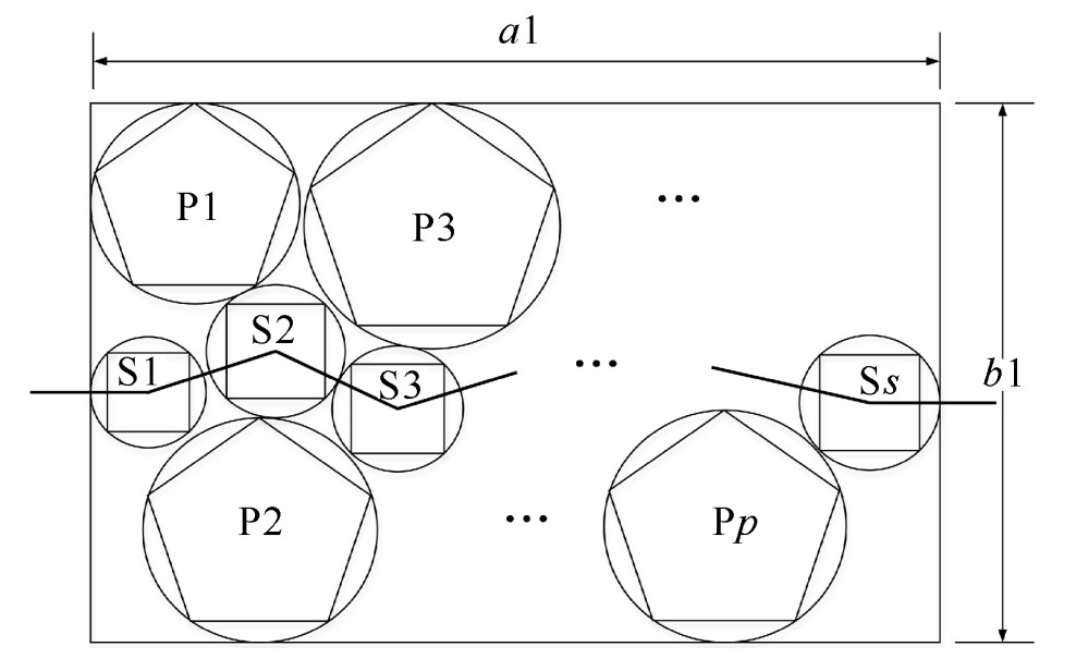
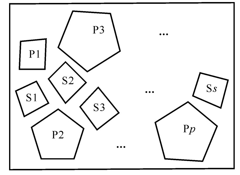
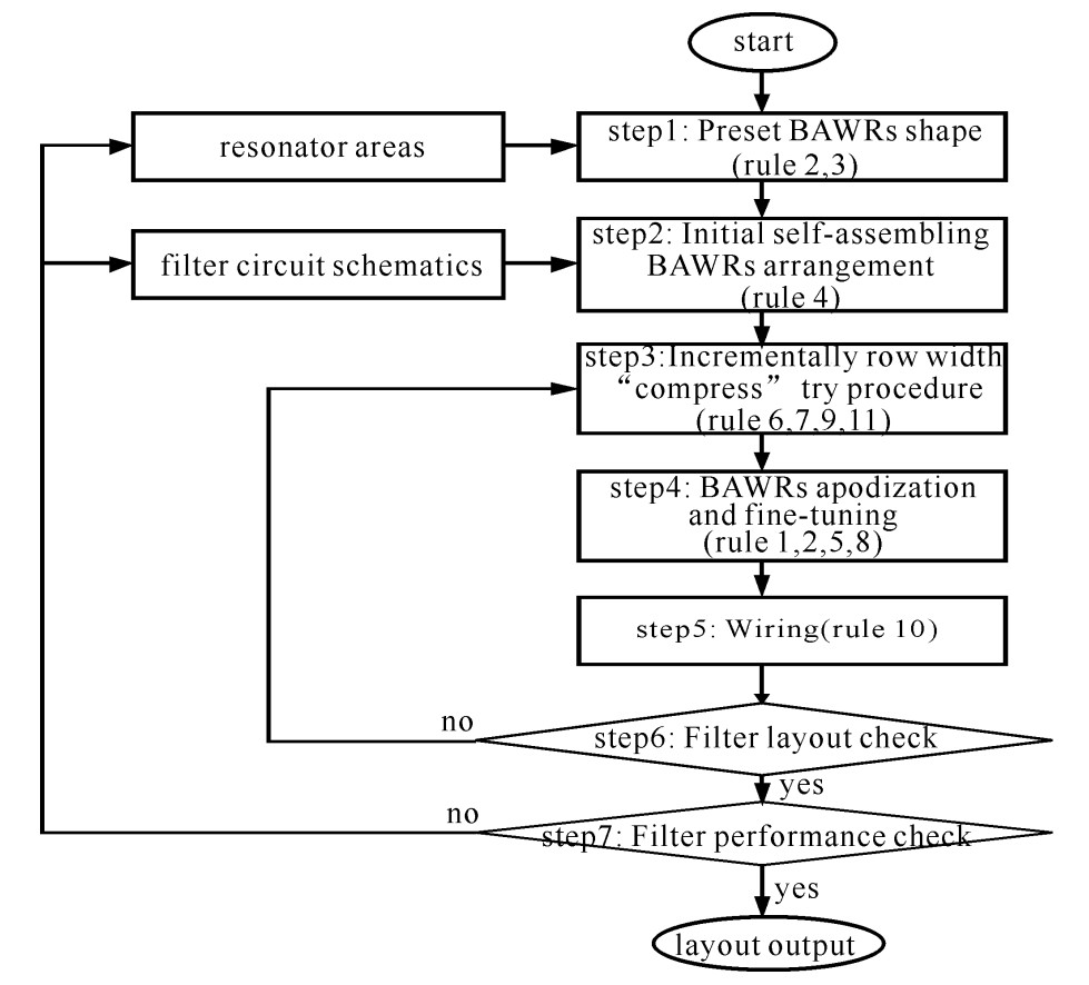
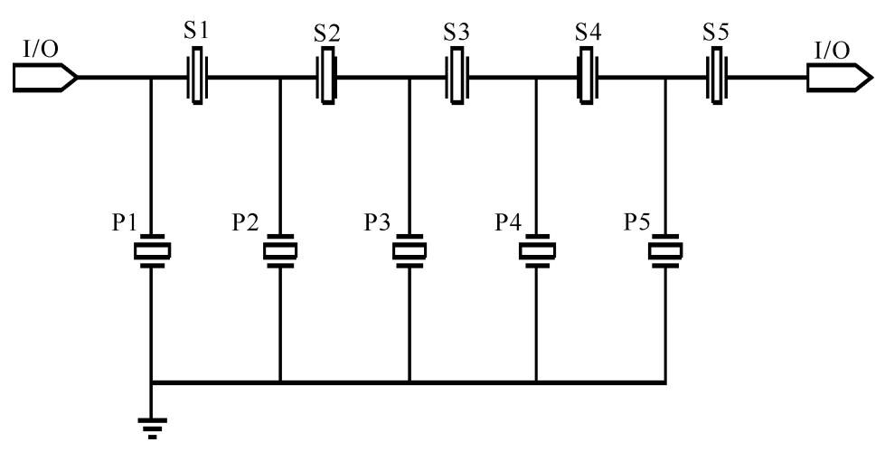
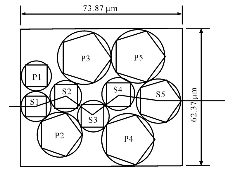
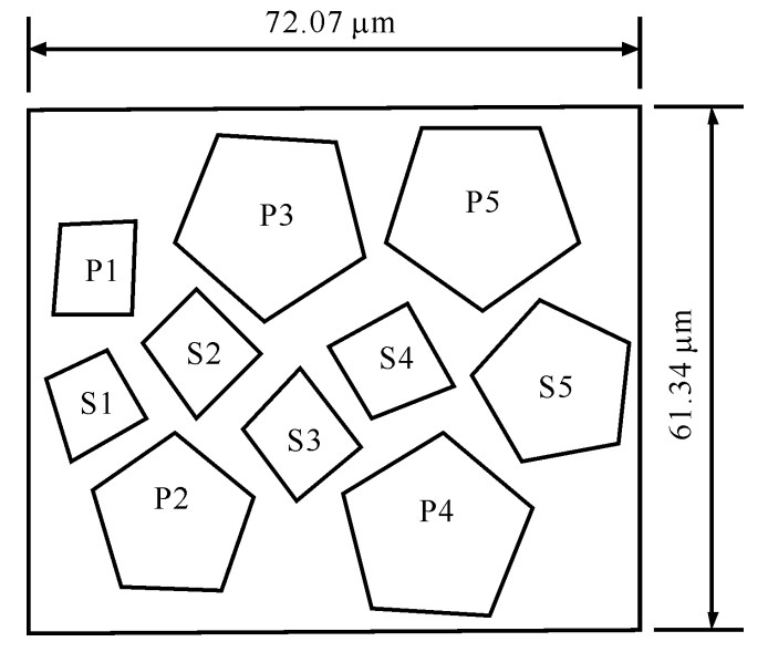
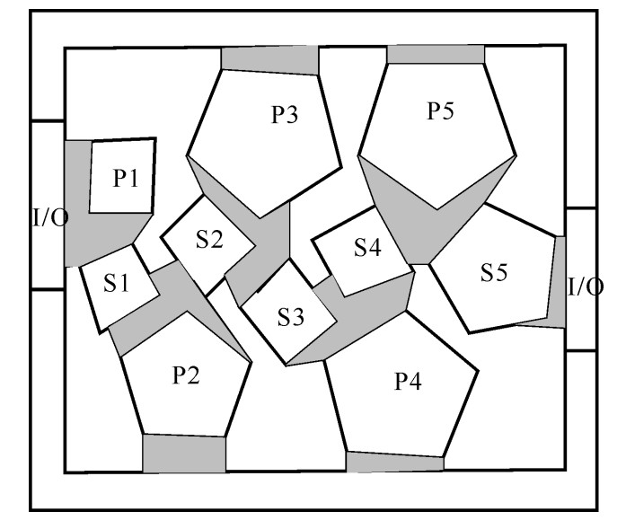
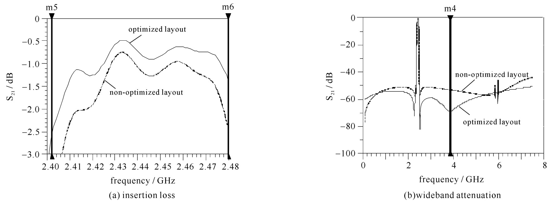
摘要: 为保证滤波器性能,缩小滤波器体积,提高晶圆上的芯片数量,提出一种体声波(BAW)梯形滤波器布局的设计方法。该方法包括11条设计准则和设计流程。11条设计准则限制体声波谐振器(BAWR)的形状、位置,BAWR之间的距离,BAWR与焊盘的距离和互连线。设计流程有7个步骤:(1)根据每个BAWR的有效面积,预设每个BAWR的形状;(2)根据BAW梯形滤波器电路结构,排列BAWR;(3)“压缩”布局;(4)对BAWR切趾、微调和旋转;(5)对BAWR和焊盘布线;(6)检测滤波器布局是否符合设计准则;(7)使用声-电磁联合仿真,验证滤波器布局结果。以10个BAWR串并联而成的5阶BAW梯形滤波器为案例,展示了该方法的设计准则和设计流程。优化后的滤波器布局面积利用率达到了44%。对比未优化的滤波器布局,利用该方法优化后的滤波器布局提高了BAW滤波器的带内插损和带外抑制。Abstract: In order to ensure the performance of the filter, reduce the volume of the filter and increase the number of chips on the wafer, a design method for the bulk acoustic wave (BAW) ladder filter is proposed. This method consists of 11 design rules and a design flow. The 11 design rules limit the shape and position of the BAW resonators (BAWRs), the distance between the BAWRs, the distance between the BAWRs and the pads and the interconnecting wire. There are 7 steps in the design flow: The first step is to preset the shape of each BAWR according to its active area value. The second step is to arrange BAWRs according to the BAW ladder filter circuit topology. The third step, "compression" layout. The fourth step, the BAWRs apodization, fine-tuning and rotation. The fifth step is to wire BAWRs and pads together. The sixth step is to detect if the layout of the filter meets the design rules. The seventh step, the use of a combined acoustic-electromagnetic BAW filter simulation method to verify the layout result. This paper presents the design rules and design flow of a 5-order BAW ladder filter with 10 series/parallel connected BAWRs. The optimized filter layout area utilization rate is 44%. Compared with the non-optimized filter layout, the optimized filter layout has lower insertion loss and higher out-of-band rejection. Thus we validate the feasibility of the layout design method.
-
Key words:
- micro electro mechanical system /
- bulk acoustic wave /
- filter /
- resonator /
- layout
-
表 1 BAWR的面积
Table 1. Area of BAWRs
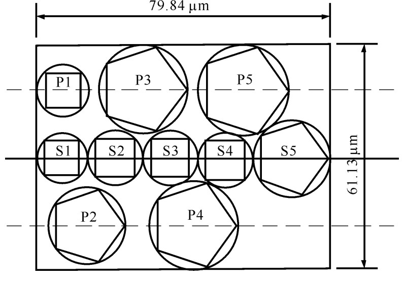
BAWR area/μm2 preset shape S1 7 260.744 1 square S2 8 968.09 square S3 8 667.61 square S4 9 120.25 square S5 19 909.21 pentagon P1 7 413.21 square P2 19 740.25 pentagon P3 27 192.01 pentagon P4 27 093.16 pentagon P5 28 056.25 pentagon -
[1] Bauer T, Eggs C, Wagner K, et al. A bright outlook for acoustic filtering: A new generation of very low-profile SAW, TC SAW, and BAW devices for module integration[J]. IEEE Microwave Magazine, 2015, 16(7): 73-81. doi: 10.1109/MMM.2015.2429512 [2] Zhang Y, Chen D. Multilayer integrated film bulk acoustic resonators[M]. Shanghai: SJTU Press, 2012. [3] Gao Yang, Zhou Bin, He Yi, et al. Analysis of electromagnetic compatibility of thin film bulk acoustic resonator[J]. Yadian Yu Shengguang/Piezoelectrics & Acoustooptics, 2015, 37(1): 1-5. [4] 庞慰, 谢恒, 张代化, 等. 一种压电声波滤波器的设计和布局方法: 中国, 103455683A[P]. 2013-12-18.Pang Wei, Xie Heng, Zhang Daihua, et al. A design and layout method for piezo-acoustic filters: CN, 103455683A. 2013-12-18. [5] Larson Ⅲ J D, Ruby R C, Bradley P. Bulk acoustic wave resonator with improved lateral mode suppression: EP, US6215375[P]. 2001. [6] Shirakawa A A, Thalhammer R, Jamneala T, et al. Bulk acoustic wave-coupled resonator filters: Concept, design, and application[J]. International Journal of RF and Microwave Computer-Aided Engineering, 2011, 21(5): 477-485. doi: 10.1002/mmce.20552 [7] Tag A, Chauhan V, Weigel R, et al. Multiphysics modeling of BAW filters[C]//IEEE Ultrasonics Symposium. 2015: 1-4. [8] Marco F, Tullio R. Electromagnetic modeling of thin-film bulk acoustic resonators[J]. IEEE Trans Microwave Theory and Techniques, 2004, 52(11): 2496-2502. doi: 10.1109/TMTT.2004.837152 [9] Gao Yang, Zhou Bin, He Yi, et al. Electromagnetic compatibility analysis method for FBAR devices[J]. Applied Mechanics & Materials, 2015, 719/720: 452-460. https://www.researchgate.net/publication/271713171_Electromagnetic_Compatibility_Analysis_Method_for_FBAR_Devices [10] Bi F Z, Barber B P. Bulk acoustic wave RF technology[J]. IEEE Microwave Magazine, 2008, 9(5): 65-80. doi: 10.1109/MMM.2008.927633 -


 下载:
下载:
