Estimation and measurement of optical turbulence over land and offshore
-
摘要: 基于Monin-Obukhov相似性理论,采用MARIAH算法,利用成都和茂名两个地区、两个高度层上的温度、湿度、风速等常规气象参数估算折射率结构常数,并对估算值与温度脉动仪测量值进行比较分析。结果显示:利用常规气象参数估算得到的成都与茂名的折射率结构常数在变化趋势及量级上基本符合温度脉动仪测量值。成都和茂名的折射率结构常数估算值与测量值的相关系数分别为0.86与0.92,平均绝对值偏差分别为0.410与0.414。因此,采用MARIAH算法估算陆地和近海面大气光学折射率结构常数是可行的;茂名中午时刻的折射率结构常数峰值比成都大一个量级。Abstract: The refractive index structure constant is estimated and compared with measured values from micro-thermometer by using the meteorological parameters of Chengdu and Maoming, such as temperature, humidity and wind speed on two altitudes. The estimated model adopts MARIAH algorithm, which is based on the Monin-Obukhov similarity theory. The result shows that it is feasible to calculate the structure parameter by MARIAH algorithm. The trend and order of magnitude of the estimated structure constant fit well to that of the measured data. The correlation coefficients between estimated and measured values of two places are 0.86 and 0.92 while the mean absolute error values are 0.410 and 0.414 respectively. Besides, the estimated structure constant of Maoming is one order of magnitude larger than that of Chengdu.
-
大气湍流是大气中普遍存在的一种随机运动现象,它会使空气的折射率发生随机变化。大气湍流强度一般用折射率结构常数Cn2表征[1]。当激光在大气湍流中传播时,由大气湍流引起的空气折射率随机起伏会导致激光波阵面产生畸变,破坏激光的相干性,导致激光传输质量受到严重影响[2]。自20世纪70年代以来,国内外对大气折射率结构常数的估算模式已经进行了大量的研究工作。已有的大气湍流估算模式主要有以下四种:第一是根据表面能量平衡方程得到表面湍流通量,进而估算出湍流强度[3];第二是利用统计回归的方法,建立折射率结构常数与辐射通量、气温、湿度、风速的回归方程,估算出折射率结构常数[4];第三是利用数值预报的方法,预报出折射率结构常数[5];第四是依据Monin-Obukhov相似理论,输入一个高度层上的温度、湿度、风速和地表面(或海表面)湿度、温度,并计算得到表面粗糙度,然后通过迭代方法估算出大气湍流强度[6]。例如Hutt[7]利用相似理论估算得到了陆地的折射率结构常数;戴福山等[8]通过对普适函数的修正,利用我国海面气象水文观测数据估算了海面光学湍流。本文在Monin-Obukhov相似理论的基础上,采用MARIAH算法,可直接估算得到近地面折射率结构常数, 并对两地的折射率结构常数估算值和实测值进行了对比与分析。与传统计算方法相比,该算法利用成都和茂名两个地区、两个高度层上的温度、湿度和风速等气象参数,无需计算表面粗糙度也不需通过迭代方法求解。
1. 大气折射率结构常数估算
1.1 大气湍流理论
已知在可见光和近红外波段,大气折射率结构常数Cn2与温度结构常数(CT2)、湿度结构常数(Cq2)、温湿相关项结构常数(CTq)的关系为
(1) 式中:A与B是与温度、压强、波长有关的系数,当波长为0.55 μm时,A=79×10-6p/T2,B=-56.4×10-6。p为空气压强(hPa),T为温度(K)。
结构函数CT2,Cq2,CTq的定义为
(2) 式中:rTq是温湿度相关系数,当ΔT/Δq < 0时,rTq≈0.5,当ΔT/Δq>0,rTq≈0.8;T*是特征温度; q*是特征湿度; 相似性函数fT,fq,fTq选取Wyngaard公式。
1.2 湍流特征尺度
根据相似理论,在满足水平均匀、平稳、常通量等条件下的近地面层,风速、温度、湿度无量纲化的普适廓线方程表达式为
(3) 式中:u*为摩擦速度;u是风速(m/s);q是比湿(g/g);k是Von-Karman常量,其值通常取0.4;ϕm(z/L), ϕH(z/L), ϕq(z/L)分别是风速、温度、湿度的无量纲稳定度参数z/L的普适函数。
本文采用MARIAH算法[9],将式(3)的偏微分方程用两个不同高度层的差值代替,用离散值代替连续值,而不是像文献[7]一样,对式(3)进行积分运算。MARIAH算法的参数计算表达式为
(4) 式中:Δu=u(z1)-u(z2); ΔT=T(z1)-T(z2); Δq=q(z1)-q(z2),Δlnz=lnz1-lnz2, z1和z2分别表示低层与高层的高度,依据Dyer和Hicks的公式,有
(5) 式中: L是Monin-Obukhov长度,表达式为
(6) 式中: g表示重力加速度。再将式(6)代入式(7)中,可以得到L用两个高度层的常规气象参数表示的关系式
(7) 因此,输入两个高度层的风速、温度、湿度,由公式(7)可计算得到Monin-Obukhov长度L的值,然后带入式(5)和式(4)中,可求得特征尺度u*, T*, q*的值,再代入Wyngaard公式和公式(2)中,求得结构常数CT2, Cq2, CTq的值,最后代入式(1),可计算得到大气折射率结构常数Cn2的值。
1.3 实验设备
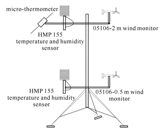
利用如图 1所示的仪器设备分别在成都与茂名开展实验测量。实验设备主要安装在具有两个高度层的三脚架上。分别在0.5 m和2 m高度处安装了Young风速风向传感器(05106)和温湿度传感器(HMP 155),测量数据用于光学湍流的模式估算。在2 m高度还安装了温度脉动仪,进行光学湍流的实时测量,测量的数据用于与光学湍流估算值进行比对。实验观测期间,天气状况良好。表 1给出了近地面大气参数测量系统传感器技术参数。
表 1 近地面大气参数测量系统传感器技术参数Table 1. Technical parameters of sensors for near-surface atmospheric parameters measurementname model accuracy temperature/RH probe HMP155 temperature: < 0.1 ℃;RH: ±1% RH(0~90%RH), ±1.7%RH(90%~100%RH) wind monitor 05106 wind speed: ±0.3 m/s, wind direction: ±3° micro-thermometer MT1 system noise level corresponding to DT of 2×10⁻³ ℃ 2. 估算结果与实测结果对比
2.1 估算结果
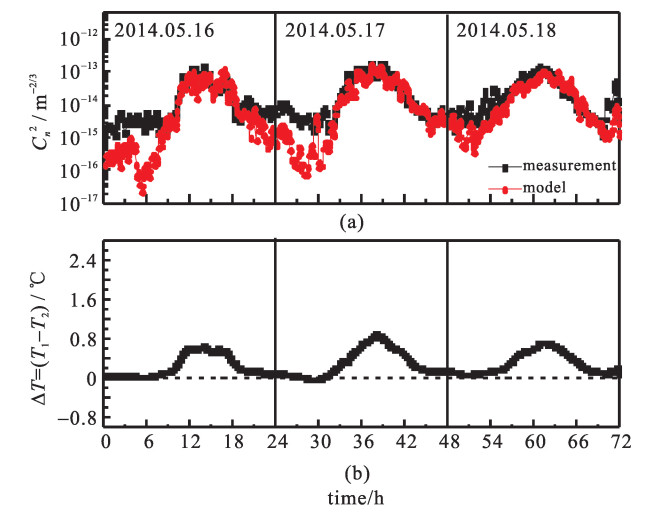
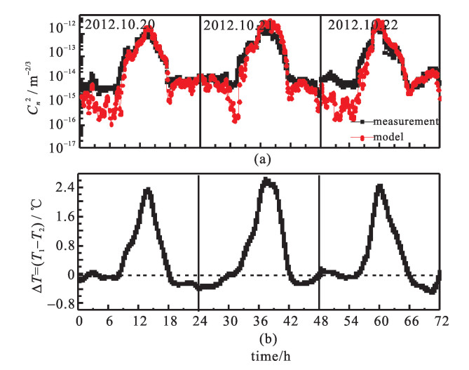
成都和茂名所处的地理位置和环境有很大差异。成都实验地点在成都的双流县(31°39′N,103°50′E),它位于成都平原腹地中心,海拔高度约为490 m,属亚热带湿润季风气候,且受大陆性气候的影响。茂名博贺海洋科学实验基地位于南海的海岸线上(21°27′N,111°19′E),海岸线呈东北-西南走向,南面为广阔的南海水域,北部为植被稀疏的丘陵,受到大陆性和海洋性气候的影响。图 2(a)和图 3(a)分别为成都2014年5月16日至18日和茂名2012年10月20日至22日三天的Cn2模式估算结果与温度脉动仪测量结果的日变化比较,图 2(b)和图 3(b)分别为成都和茂名的温差值变化趋势。
从图 2(a)与图 3(a)可以看出:茂名与成都的Cn2模式估算值与测量值在变化趋势上基本一致,均呈现出白天湍流强夜晚湍流弱的特征,表现出明显的日变化趋势。白天由于太阳辐射,地表温度高,大气层结不稳定,利于湍流的发展,中午一点左右达到最大值;早上8点至9点和下午18点至19点,地气能量达到平衡,湍流最弱;下午18点左右到凌晨24点这段时间,成都与茂名两地的估算值与温度脉动仪测量值吻合得相对较好,但是24点以后到早晨8点左右,模式估算值明显小于温度脉动仪测量值。此外,成都与茂名Cn2测量值在白天的最大值不同,茂名最大值能达到10-12 m-2/3,而成都只有10-13 m-2/3。
吴晓庆等[1]认为,两个高度层的温差值对该模式的估算准确性最敏感。从图 2和图 3可以看出,茂名与成都两地测量的Cn2值的趋势走向和两个高度层的温差值趋势走向一致(中午都有最大值,夜晚变化比较平缓);在夜晚的时候,成都与茂名都存在Cn2估算值低于测量值的情况,根据图 2(b)和3(b),此时ΔT趋近于0,符合文献[1]中的结论;如图 2和图 3所示,茂名的Cn2峰值比成都的大一个量级,茂名的温差值峰值在中午达到了2.5 ℃,成都的只有0.7 ℃。这可能是因为茂名测量点处于海陆交界处,陆面和海面大气交汇容易使得测量点处温度梯度较大,湍流发展更充分。
在成都与茂名下午18点左右到凌晨24点这段时间,成都的两个高度层的温差值在0.17 ℃左右,茂名的温差值都在-0.25 ℃左右,但是在这段时间,模式估算的Cn2值与测量的Cn2值吻合得相对较好。只有当两个高度层的温差值ΔT≈0 ℃的时候,该模式的估算值相对于实测值明显偏小。因此,该估算模式的适用性受到当地不同高度层温差的限制,只有在较大温差的环境中,该模式才具有很高的可行度。
2.2 估算结果统计分析
为了评估估算结果的可靠性,本文选取了平均绝对值偏差(EMA)、均方根方差(ERMS)、相关系数(Rxy)三个统计量来分析估算结果[10],相应计算表达式为
(8) (9) (10) 式中: Δi=Yi-Xi,N表示样本的总个数,Xi与Yi表示第i时刻Cn2的实际观测值与模式估算值。
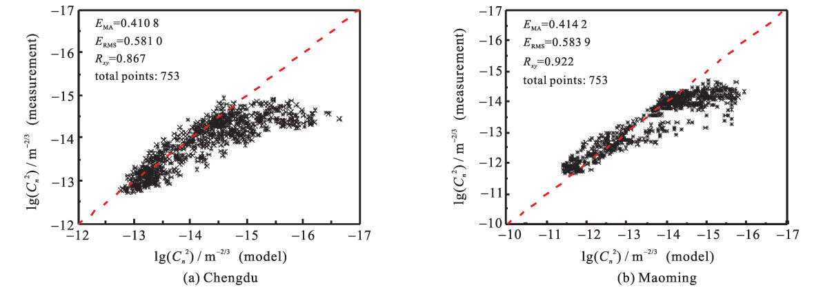
图 4为成都与茂名地区模式估算值与测量值的lg(Cn2)统计分析,结果显示,成都与茂名模式估算值与测量值的相关度分别为0.867和0.922,平均绝对值偏差分别为0.410和0.414,所以从相关性上分析,茂名估算结果与实测结果的整体趋势要好于成都;而从平均值偏差上分析,成都的估算结果与实测结果之间的量级差值要小于茂名。成都的lg(Cn2)在-12.75与-16.25之间,茂名的lg(Cn2)在-11.5与-16之间,可以看出茂名的Cn2范围大于成都的Cn2范围。且从图中可以看出,lg(Cn2)>-15时,Cn2>10-15 m-2/3,比例系数接近1,成都和茂名的估算值与实际测量值符合较好;当lg(Cn2) < -15时,Cn2 < 10-15 m-2/3,成都与茂名的模式估算值普遍小于实际测量值。
3. 结论
在成都与茂名的实验中,利用MARIAH算法估算得到的折射率结构常数与用温度脉动仪测得的结果吻合得较好。说明该算法在成都与茂名的估算结果是准确的、可行的。与传统的大气折射率结构常数的估算方法相比,MARIAH算法在保证估算值准确性的前提下,优化了估算过程。
成都与茂名的Cn2模式估算值与测量值具有明显的日变化趋势;成都与茂名因地理位置的不同,茂名Cn2的最大值要比成都的Cn2最大值大一个量级;两个高度层的温度差对Cn2的估算有很大影响,当温差趋于0的时候,大气处于稳定条件下,估算结果小于测量结果;在相关性上分析,茂名的估算结果好于成都,在偏差上分析,成都的估算结果好于茂名。
成都与茂名夜晚估算的折射率结构常数与温度脉动仪实测值存在着一定的偏差,多数情况是估算值低于测量值,原因可能有:(1)温度脉动仪受到空气中灰尘等杂物地影响,导致仪器的灵敏度下降; (2)Monin-Obukhov相似理论应用的条件是大气水平均匀、湍流充分发展、存在常通量层,但是通常在夜晚的时候,尤其是温差值ΔT≈0 ℃的时候,湍流得不到充分发展,相似理论的应用受到限制。
-
表 1 近地面大气参数测量系统传感器技术参数
Table 1. Technical parameters of sensors for near-surface atmospheric parameters measurement
name model accuracy temperature/RH probe HMP155 temperature: < 0.1 ℃;RH: ±1% RH(0~90%RH), ±1.7%RH(90%~100%RH) wind monitor 05106 wind speed: ±0.3 m/s, wind direction: ±3° micro-thermometer MT1 system noise level corresponding to DT of 2×10⁻³ ℃ -
[1] 吴晓庆, 朱行听, 黄宏华, 等. 基于Monin-Obukhov相似理论估算近地面光学湍流强度[J]. 光学学报, 2012, 32 (7): 22-28. https://www.cnki.com.cn/Article/CJFDTOTAL-GXXB201207003.htmWu Xiaoqing, Zhu Xingting, Huang Honghua, et al. Optical turbulence of atmospheric surface layer estimated based on the Monin-Obukhov similarity theory. Acta Optica Sinica, 2012, 32 (7): 22-28 https://www.cnki.com.cn/Article/CJFDTOTAL-GXXB201207003.htm [2] 李杨, 相里斌, 张文喜. 湍流大气中激光传输对傅里叶望远镜成像质量的影响[J]. 强激光与粒子束, 2013, 25 (2): 292-296. doi: 10.3788/HPLPB20132502.0292Li Yang, Xiang Libin, Zhang Wenxi. Effects of laser propagation through atmospheric turbulence on imaging quality in Fourier telescopy. High Power Laser and Particle Beams, 2013, 25 (2): 292-296 doi: 10.3788/HPLPB20132502.0292 [3] Kunkel K E, Walters D L. Modeling the diurnal dependence of the optical refractive index structure parameter[J]. Journal of Geophysical Research: Oceans, 1983, 88 (C15): 10999-11004. doi: 10.1029/JC088iC15p10999 [4] Sadot D, Kopeika N S. Forecasting optical turbulence strength on the basis of macroscale meteorology and aerosols: Models and validation[J]. Optical Engineering, 1992, 31 (2): 200-212. doi: 10.1117/12.56059 [5] 青春, 吴晓庆, 李学彬, 等. 基于天气数值预报模式预报高空光学湍流[J]. 强激光与粒子束, 2015, 27: 061009. doi: 10.11884/HPLPB201527.061009Qing Chun, Wu Xiaoqing, Li Xuebin. Forecast upper air optical turbulence based on weather research and forecasting model. High Power Laser and Particle Beams, 2015, 27: 061009 doi: 10.11884/HPLPB201527.061009 [6] Thiermann V, Lohse H, Englisch G. Modeling optical turbulence in the atmospheric boundary layer over sea[C]//Proc of SPIE. 1997, 2596: 198-203. [7] Hutt D L. Modeling and measurements of atmospheric optical turbulence over land[J]. Optical Engineering, 1999, 38 (8): 1288-1295. doi: 10.1117/1.602188 [8] 戴福山, 李有宽. 利用气象要素估算海洋大气近地层光学湍流[J]. 光学学报, 2007, 27 (2): 191-196. https://www.cnki.com.cn/Article/CJFDTOTAL-GXXB200702001.htmDai Fushan, Li Youkuan. Estimation of the optical turbulence in the marine atmospheric surface layer based on meteorological data. Acta Optica Sinica, 2007, 27 (2): 191-196 https://www.cnki.com.cn/Article/CJFDTOTAL-GXXB200702001.htm [9] Rachele H, Tunick A, Hansen F V. MARIAH—A similarity-based method for determining wind, temperature, and humidity profile structure in the atmospheric surface layer[J]. Journal of Applied Meteorology, 1995, 34 (4): 1000-1005. doi: 10.1175/1520-0450(1995)034<1000:MASBMF>2.0.CO;2 [10] Qing Chun, Wu Xiaoqing, Huang Honghua, et al. Estimating the surface layer refractive index structure constant over snow and sea ice using Monin-Obukhov similarity theory with a mesoscale atmospheric model[J]. Optics Express, 2016, 24 (18): 20424. doi: 10.1364/OE.24.020424 期刊类型引用(3)
1. 赵慧,张守宝,王红光,刘萱,林乐科,张银辉,蔡文炳. 基于WRF模式预报的微波湍流特性研究. 电波科学学报. 2022(02): 321-327 .  百度学术
百度学术2. 陆泽辉,郭振锋,孟森森,刘波,刘海锋,林炜,姚远,郭盟. 室外大气折射率结构常数实时测量研究. 遥测遥控. 2022(04): 31-36 .  百度学术
百度学术3. 樊文科,冯菊,周亮,廖成. 基于抛物方程的湍流散射研究. 电子测量技术. 2019(01): 6-10 .  百度学术
百度学术其他类型引用(6)
-


 下载:
下载:


 下载:
下载:


