

-
Abstract: High power microwave research is moving into the high rep-rate regime and it will be common that an electron beam accelerator operates more than a million shots per year. As a result, accumulated bremsstrahlung X-ray produced by the electron beam collector is no longer negligible, and shielding is necessary for personnel safety. By using the BEAMnrc Monte-Carlo code, a typical collector for a ring beam usually used in HPM tube is simulated, which has beam voltage 1 MV, beam current 10 kA, pulse duration 100 ns and rep-rate 100 Hz. The results show the spectrum and spatial distribution of the X-ray generated at the collector. The attenuation factor of the X-ray is estimated from the simulation. The estimation of the skyshine radiation is also considered for the roof of the building.
-
High power microwave(HPM) researches have gained a lot of popularity nowadays[1-2], and the operation of the facilities has moved from the single-shot to the rep-rate regime. Repetition rate of 100 Hz is common, for example, for the Sinus e-beam accelerators developed in Russia[3] and similar facilities around the world. It is normal that an accelerator will operate more than a million shots a year. Because most of the energy of the intense relativistic electron beam deposits on the collector, there will be bremsstrahlung radiation and X-ray will be produced. As accelerators become compact and widely available, shots number increases dramatically, and the cost of X-ray shielding increases as well.
There are strict laws and rules regarding to ionization radiation safety. In China, the standard GB 18871-2002 regulates the radiation safety level [4] for different situations. Usually the dose received should not exceed 1 mSv per year for an ordinary person. The required protection and shielding can be calculated from the attenuation of shielding materials, such as concrete, lead, steel, etc., which are available in handbooks [5], for given accelerator parameters. However, to design the shielding according to the handbooks will lead to very high cost, as most handbooks give the protection for the very worst case. It is always useful to know more about the radiation details of the specific accelerator with a simulation before a general design.
In this paper, the BEAMnrc Monte-Carlo code[6] is used for radiation calculation and dose estimation. A cylindrical stainless steel collector for a ring beam usually found in HPM tubes is simulated. The input beam has voltage 1 MV, current 10 kA, pulse duration 100 ns and rep-rate 100 pps. The calculation can be rescaled for other parameters of the beam collector. Skyshine radiation is also considered for the roof of the building.
1. The geometry and the model
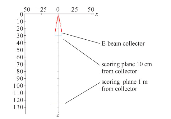
The Monte-Carlo code used to calculate the X-ray distribution is BEAMnrc, which is based on the EGSnrc code system[6]. Fig. 1 shows the axisymmetric 3-D geometry of electron beam hitting the stainless steel collector (mostly Fe element). The source at the origin emits 1 MeV electrons in a cone surface with angle 10° around the axis, to mimic the beam usually found in backward wave oscillators (BWOs)[1-2]. The Fe cylinder collector is of 2 mm thickness in the wall and the bottom. The background is filled with vacuum for z < 30 cm, and air for z>30 cm. Two scoring planes are used to receive scattered electrons and photons.
 Figure 1. Geometry of the BEAMnrc input (unit: cm)
2. Simulation results
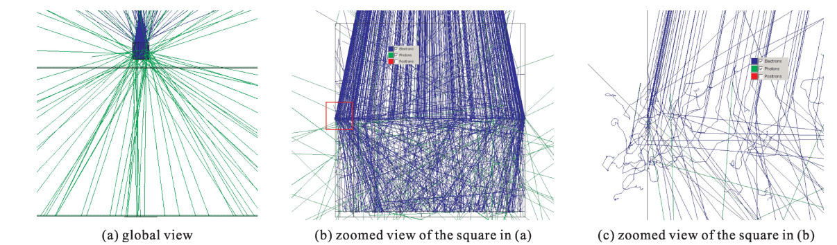
106 histories were run with the code. Fig. 2 gives 1 000 sample tracks of electrons (blue lines) and photons (green lines). There are no positrons since the incident beam energy is merely 1 MeV, too low to cause pair production. It is easy to note from Fig. 2(c) the electrons have very small free path within the collector, and some electrons are scattered backward into vacuum. Most of the electrons travel less than 0.5 mm in the collector, and no electrons escape to the air. The X-ray photons have much larger free path, and most of the photons travel forward.
 Figure 2. Tracks of electrons (blue lines) and photons (green lines)
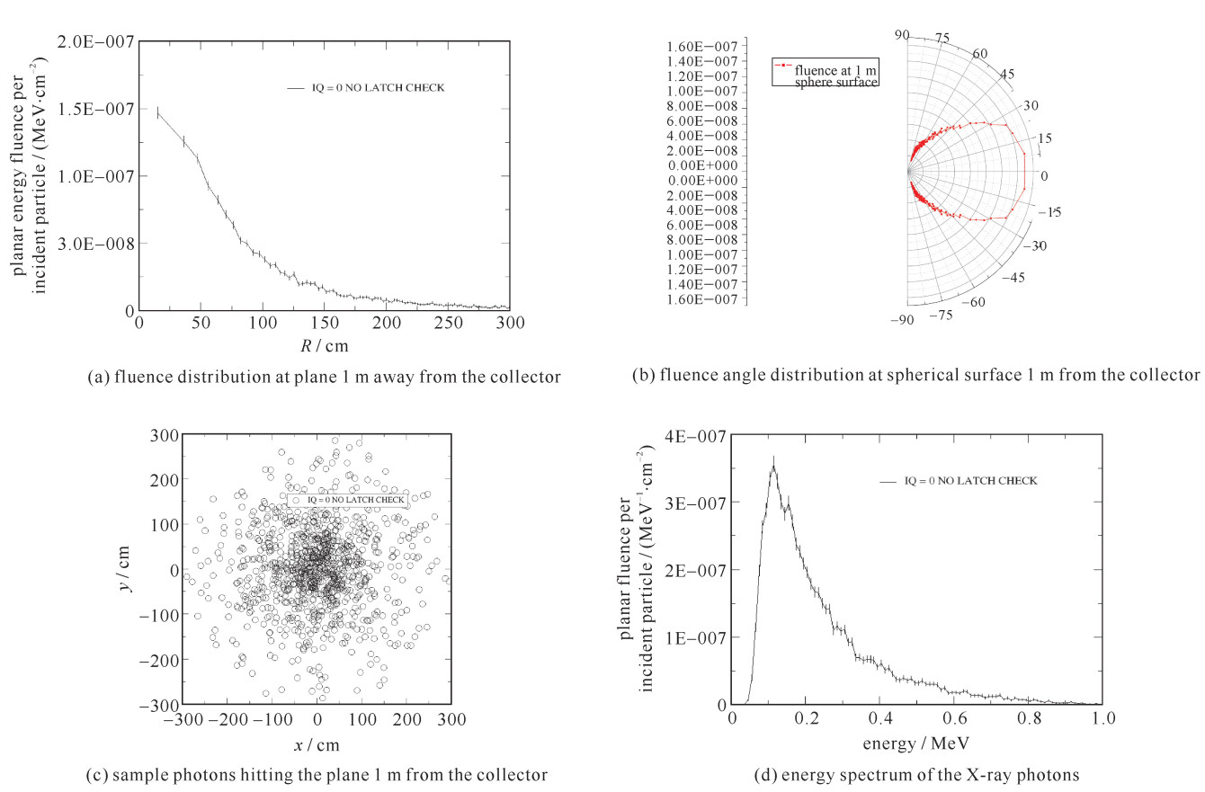
Table 1 gives the statistical result for 106 histories at the scoring plane 1 m away from the e-beam collector, with the number of photons normalized to 1 incident electron. The scoring plane is divided into 20 annular zones surrounding the axis, with each zone 20 cm wide, and zone 1 closest to the axis. From Table 1 the X-ray photons' spectrum and spatial distribution (proportional to energy fluence) are plotted, as shown in Fig. 3. All uncertainties are less than 5%. The generated X-ray is a broad beam, with the maximum radiation in forward direction and the half angle up to 45°. It means that the off-axis radiation is not negligible.
Table 1. Statistical fluence at scoring plane 1 m from the collectorzone number of photons fluence/cm-2 photon energy/MeV angle with z-axis/(°) 1 7.890E-04(1±3.56%) 6.355E-07(1±3.56%) 0.248(1±2.4%) 8.220(1±1.4%) 2 2.001E-03(1±2.24%) 5.580E-07(1±2.24%) 0.251(1±1.5%) 17.605(1±0.4%) 3 2.595E-03(1±1.96%) 4.637E-07(1±1.96%) 0.252(1±1.3%) 26.782(1±0.2%) 4 2.584E-03(1±1.97%) 3.592E-07(1±1.97%) 0.244(1±1.3%) 34.961(1±0.2%) 5 2.203E-03(1±2.13%) 2.629E-07(1±2.13%) 0.237(1±1.4%) 42.051(1±0.1%) 6 1.880E-03(1±2.30%) 2.027E-07(1±2.31%) 0.236(1±1.5%) 47.751(1±0.1%) 7 1.580E-03(1±2.51%) 1.590E-07(1±2.52%) 0.228(1±1.6%) 52.451(1±0.1%) 8 1.314E-03(1±2.76%) 1.259E-07(1±2.76%) 0.231(1±1.8%) 56.322(1±0.1%) 9 1.025E-03(1±3.12%) 9.493E-08(1±3.12%) 0.217(1±2.0%) 59.592(1±0.1%) 10 8.830E-04(1±3.36%) 7.958E-08(1±3.37%) 0.235(1±2.2%) 62.265(1±0.1%) 11 7.820E-04(1±3.57%) 6.928E-08(1±3.58%) 0.231(1±2.3%) 64.642(1±0.1%) 12 6.540E-04(1±3.91%) 5.699E-08(1±3.91%) 0.215(1±2.6%) 66.579(1±0.0%) 13 5.590E-04(1±4.23%) 4.807E-08(1±4.23%) 0.219(1±2.7%) 68.250(1±0.0%) 14 4.620E-04(1±4.65%) 3.931E-08(1±4.65%) 0.212(1±3.0%) 69.714(1±0.0%) 15 4.050E-04(1±4.97%) 3.431E-08(1±4.97%) 0.223(1±3.2%) 71.080(1±0.0%) 16 5.690E-04(1±4.19%) 2.542E-08(1±4.20%) 0.207(1±2.6%) 73.062(1±0.1%) | Show Table DownLoad:
CSV
DownLoad:
CSV
 Figure 3. Fluence distribution and spectrum of the photons
3. Dose calculation and shielding estimation
Dose for each zone is calculated from the fluence obtained in Section 2 by Eq.(1).
D=EΦμenρ (1) where D is the dose, E is the photon energy, Φ is the fluence, and μen/ρ is the mass energy absorption coefficient. As the human body is mostly composed of water, μen/ρ for water is used, which is about 0.03 cm2/g for photons of energy 0.1-1 MeV [7].
The calculated results are as follows:
1) for a single 1 MeV incident electron, the maximum dose at 1 m place is less than 1×10-18 Gy; most of the photons have energy less than 0.5 MeV, with the peak about 0.1 MeV, and the average about 0.25 MeV;
2) for an e-beam of 10 kA and 100 ns, there are 1.6×10¹⁶ electrons;
3) for one shot, the maximum dose at 1 m is 16 mGy, which is 16 times higher than the safety standard for one year.
The results show that shielding is necessary for a person operating or near the accelerator. Shielding attenuation is calculated from Eq. (2) [7].
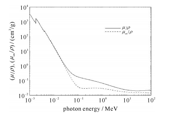
II0=exp(−μρt) (2) where I/I0 is the attenuation, t is the thickness of the material, ρ is the density, and μ/ρ is the mass attenuation coefficient, as shown in Fig. 4 for ordinary concrete [7].
 Figure 4. Mass attenuation coefficient for ordinary concrete[7]
We consider a typical arrangement. The accelerator is placed 5 m from the wall. The maximum dose at the inside surface of the wall will be 0.64 mGy according to the inverse square law. From Eq.(2) the concrete wall of thickness of 750 mm can provide 40 dB attenuation for photons of 0.5 MeV, and more attenuation for photons of 0.1 MeV. Outside the wall, the maximum dose is below safety level (1 mGy per year) for 15 000 shots.
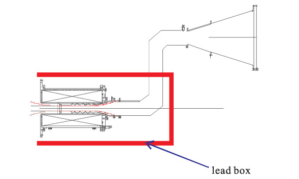
Additional shielding is needed for 106 shots per year. It will be cost effective to shield locally using lead sheet near the collector rather than to build thicker walls. Lead sheet of 5 cm will provide attenuation of 30 dB. Thus, 5 cm thickness of lead sheet around the collector and 750 mm thickness of concrete wall will allow the accelerator of parameters 1 MV, 10 kA and 100 ns placed 5 m from the wall, to run 15×106 shots per year safely. Fig. 5 gives a suggested shielding scheme. As the maximum radiation lies in the axis of the e-beam, a bending waveguide is inserted between the microwave source and the antenna, so that enough attenuation is achieved.
 Figure 5. Suggested lead shielding scheme
4. Skyshine considerations
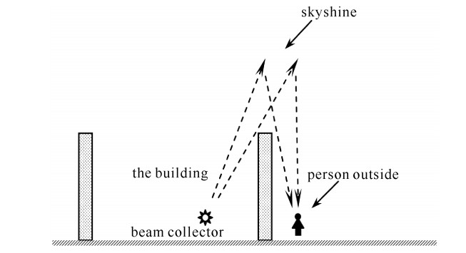
The estimation made above does not consider the skyshine factors. If the building has no roof or very thin roof, as shown in Fig. 6, people outside the building may still be harmed by the radiation reflected from the roof and the air above.
 Figure 6. Skyshine diagram
The skyshine dose rate can be estimated by Eq. (3)[5]
˙H=2.5×10⁷(Bx s˙D0Ω1.3)(dids)2 (3) where ˙H is the absorbed dose rate in nSv/h, di is the height of the roof plus 2 m, ds is the horizontal distance from source in meters, Bxs is the attenuation factor of the roof, ˙D0 is the dose rate 1 m from the source in unit Gy/h, and Ω is the solid angle in steradians, and it is estimated to be π.
Since dose is proportional to dose rate, we can replace the rate variables in Eq.(3) with dose variables. From the result in Section 3, 16 mGy is the maximum dose at 1 m from the collector if no lead sheet is used. Assuming that there is no roof, thus Bxs=1; and the wall is 8 m high and the person is 6 m from the accelerator. Then dose for one single shot from the skyshine will be
2.5×107×16×0.001×π1.3[6×(8+2)]2=0.16μSv (4) So only 6 000 shots per year is allowed if there is no attenuation at the roof. For roofs of 20 cm concrete, 10 dB attenuation is provided, and shots can be increased to 60 000. Additional attenuation is necessary for more shots. If lead sheet of 5 cm thickness is placed above the collector, 6×10⁶ shots are possible.
We should note that the estimation above is the worst-case scenario. Firstly, the maximum radiation is not directed to the sky; secondly, the occupancy factors [5] should be considered, as the chance of people staying at a particular region is low.
5. Summary
The X-ray radiation dosage and shielding for a repetitive accelerator driving high power microwave is estimated. The Monte-Carlo simulation code BEAMnrc can give a detailed spectrum and spatial distribution information of X-ray generated at the collector and it is helpful for shielding design estimations. For an accelerator to run 106 shots a year, attenuation at the wall, the roof and the collector is necessary. The calculation can be easily re-scaled for other parameters of the HPM accelerator.
-
Table 1. Statistical fluence at scoring plane 1 m from the collector
zone number of photons fluence/cm-2 photon energy/MeV angle with z-axis/(°) 1 7.890E-04(1±3.56%) 6.355E-07(1±3.56%) 0.248(1±2.4%) 8.220(1±1.4%) 2 2.001E-03(1±2.24%) 5.580E-07(1±2.24%) 0.251(1±1.5%) 17.605(1±0.4%) 3 2.595E-03(1±1.96%) 4.637E-07(1±1.96%) 0.252(1±1.3%) 26.782(1±0.2%) 4 2.584E-03(1±1.97%) 3.592E-07(1±1.97%) 0.244(1±1.3%) 34.961(1±0.2%) 5 2.203E-03(1±2.13%) 2.629E-07(1±2.13%) 0.237(1±1.4%) 42.051(1±0.1%) 6 1.880E-03(1±2.30%) 2.027E-07(1±2.31%) 0.236(1±1.5%) 47.751(1±0.1%) 7 1.580E-03(1±2.51%) 1.590E-07(1±2.52%) 0.228(1±1.6%) 52.451(1±0.1%) 8 1.314E-03(1±2.76%) 1.259E-07(1±2.76%) 0.231(1±1.8%) 56.322(1±0.1%) 9 1.025E-03(1±3.12%) 9.493E-08(1±3.12%) 0.217(1±2.0%) 59.592(1±0.1%) 10 8.830E-04(1±3.36%) 7.958E-08(1±3.37%) 0.235(1±2.2%) 62.265(1±0.1%) 11 7.820E-04(1±3.57%) 6.928E-08(1±3.58%) 0.231(1±2.3%) 64.642(1±0.1%) 12 6.540E-04(1±3.91%) 5.699E-08(1±3.91%) 0.215(1±2.6%) 66.579(1±0.0%) 13 5.590E-04(1±4.23%) 4.807E-08(1±4.23%) 0.219(1±2.7%) 68.250(1±0.0%) 14 4.620E-04(1±4.65%) 3.931E-08(1±4.65%) 0.212(1±3.0%) 69.714(1±0.0%) 15 4.050E-04(1±4.97%) 3.431E-08(1±4.97%) 0.223(1±3.2%) 71.080(1±0.0%) 16 5.690E-04(1±4.19%) 2.542E-08(1±4.20%) 0.207(1±2.6%) 73.062(1±0.1%)  下载: 导出CSV
-
[1] Benford J, Swegle J A, Shamiloglu E. High power microwaves[M]. 2nd ed. New York: Taylor & Francis, 2007. [2] Zhang Jiande, Ge Xingjun, Zhang Jun et al. Research progress on Cherenkov and transit-time high-power microwave sources at NUDT[J]. Matter and Radiation at Extremes, 2016, 1(3): 163-173. [3] Mesyats G A, Korovin S D, Gunin A V, et al. Repetitively pulsed high-current accelerators with transformer charging of forming lines[J]. Laser and Particle Beams, 2003, 21: 197-209. [4] GB 18871-2002, Basic standards for protection against ionizing radiation and for the safety of radiation sources[S]. [5] National Council on Radiation Protection and Measurements. Structural shielding design and evaluation for megavoltage X- and gamma-ray radiotherapy facilities[R]. NCRP Report No. 151, 2005. [6] Rogers D W O, Walters B, Kawrakow I. BEAMnrc User's Manual[R]. NRC Report PIRS-509A (rev L), 2013. [7] NIST SRD126. Tables of X-ray mass attenuation coefficients and mass energy absorption coefficients[DB/OL]. https://www.nist.gov/ pml/x-ray-mass-attenuation-coefficients. -

 DownLoad:


 点击查看大图

计量
- 文章访问数: 1475
- HTML全文浏览量: 434
- PDF下载量: 108
- 被引次数: 0
