

-
摘要: BEPCⅡ新参量流强探测器在束流高流强对撞模式下存在严重发热问题。为了稳定和精确的测量,对可能的发热原因进行了综合讨论,针对真空盒发热问题利用CST进行尾场模拟,以本征模计算得到稳态温度分布。对探测器发热问题利用等效的反射阻抗计算方法得到陶瓷狭缝的截止频率,从而有针对性地提出了实用的解决方案并得到了理想的实验结果。实验基本解决了BEPCⅡ探测器的发热问题,对今后流强探测器的改进和未来流强探测器的研发和设计有指导意义。Abstract: The new parametric current transformer (NPCT) in BEPC Ⅱ has heating problem in high current collide mode.To find the causes and perform stable and precise measurement, wakefield simulation and eigenmode calculation have been carried out by CST, and the steady-state temperature distribution is calculated.The cut-off frequency of ceramic gap is obtained by equivalent reflection-impedance calculation.A practical solution is put forward according to the analysis, and ideal experimental results are obtained.The experiment basically solves the heating problem, it could be a guide for current transformer (CT) improvement and applied to CT designs in the future.
-
Key words:
- CST /
- new parametric current transformer /
- heating problem /
- BEPC Ⅱ
-
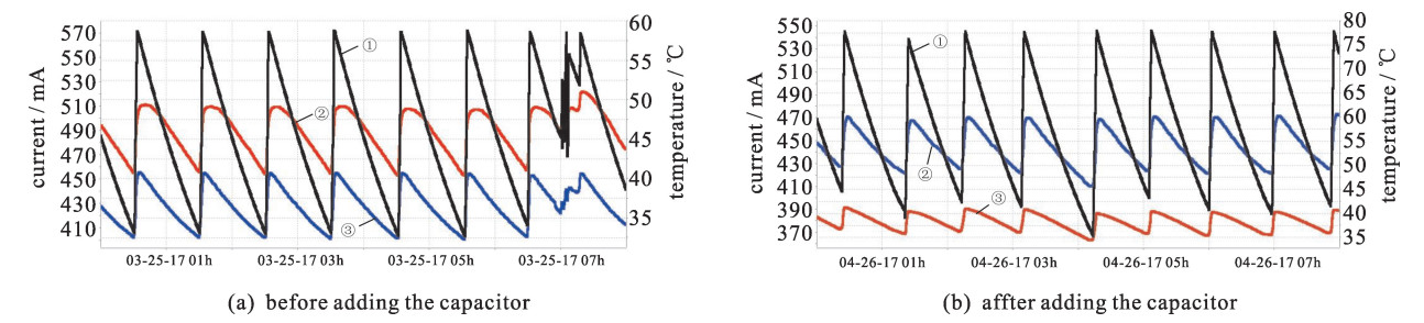
Figure 7. Beam current(①), sensor temperature(②), chamber temperature(③) before and after adding the capacitor
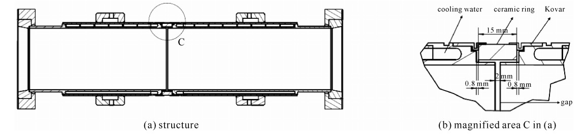
Table 1. Vacuum chamber parameters
component material data pipe steel 316 inner diameter: 96 mm, outer diameter: 111 mm water interlayer water thickness: 2 mm ceramic gap 95%Al2O3 width: 15 mm seal ring Kovar \\  下载: 导出CSV
-
[1] NPCT manual[DB/OL]. http://www.bergoz.com/. [2] Strehl P. Beam instrumentation and diagnostics[M]. Berlin: Springer-Verlag, 2006: 34-35. [3] Lipka D. Temperature simulation NPCT at PETRAⅢ[DB/OL]. https://mdi.desy.de/sites2009/site_mdi/content/e37820/e37920. [4] CST Studio Suite Help[M]. Computer Simulation Technology, 2017. [5] Tian Minbo. Magnetic materials[M]. Beijing: Tsinghua University Press, 2011: 61-63. [6] Tian Lihong. Circuit analysis[M]. Nanjing: Southeast University Press, 2016: 168-172. [7] Jian Qimin. Electromagnetism[M]. Beijing: Higher Education Press, 2010: 72-75. [8] Auerkari P. Mechanical and physical properties of engineering alumina ceramic[R]. VTT research notes 1792: 11. [9] Dupont Kapton summary of properties[DB/OL]. http://www.dupont.com. -


 点击查看大图
图(7) / 表(1)
计量
- 文章访问数: 1162
- HTML全文浏览量: 303
- PDF下载量: 76
- 被引次数: 0
