Assessing immunity of power systems to effects of high-voltage pulses with power on
-
Abstract: The results of investigation of flashovers and damages of power line insulators due to high voltage pulses with power on and power off have shown that joint action of a pulse disturbance and operating voltage of a power line can lead to catastrophic phenomena in power supply systems. High-voltage transformers are much more important and expensive elements of such systems. A set of ways of transformers tests to joint action of pulse disturbance and operating voltage of a high-voltage power line is presented in this article.
-
Key words:
- pulse disturbance /
- operating voltage /
- joint action /
- high-voltage transformers
-
There is an opinion that the most sensitive to the effects of pulse disturbances are the technical systems incorporating semiconductor devices, while high-voltage equipment is immune against them. This conclusion is based on the results of tests of high-voltage equipment when the operating voltage has not been simulated (power off). But even short duration voltage pulses, such as those created by HEMP or HPEM threats, are capable to initiate a spark short circuit. This short circuit can outgrow into an arc flashover under the effect of the operating voltage. As a result, the destruction of insulators and the failure of the high-voltage equipment can take place. Such effects can lead to catastrophic phenomena in power supply systems. Therefore, it is important to investigate flashovers and damages of power supply system elements due to high voltage pulses with power on and power off. A set of publications were devoted to the investigation. For example, the results of investigation of flashovers and damages of power line insulators due to high voltage pulses with power on and power off are described in Refs.[1-4]. These investigations have shown that high-voltage insulators could be destroyed as a result of joint action of a pulse disturbance and operation voltage of a power line.
However, insulators are not the most important elements of power systems. High-voltage transformers are much more important and expensive elements. Our thoughts concerning ways of transformer test to joint action of pulse disturbance and operating voltage of a high-voltage power line are presented in this article.
1. Transformer test similar to the one used for testing high-voltage insulators
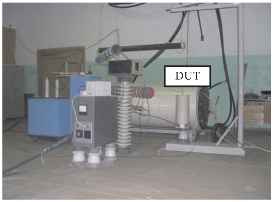
This test can be performed using the equipment developed for testing insulators of high-voltage power supply lines. General view of the experimental setup is shown in Fig. 1. The setup consists of two simulators, namely, a high-voltage pulse simulator and a power line operating voltage simulator.
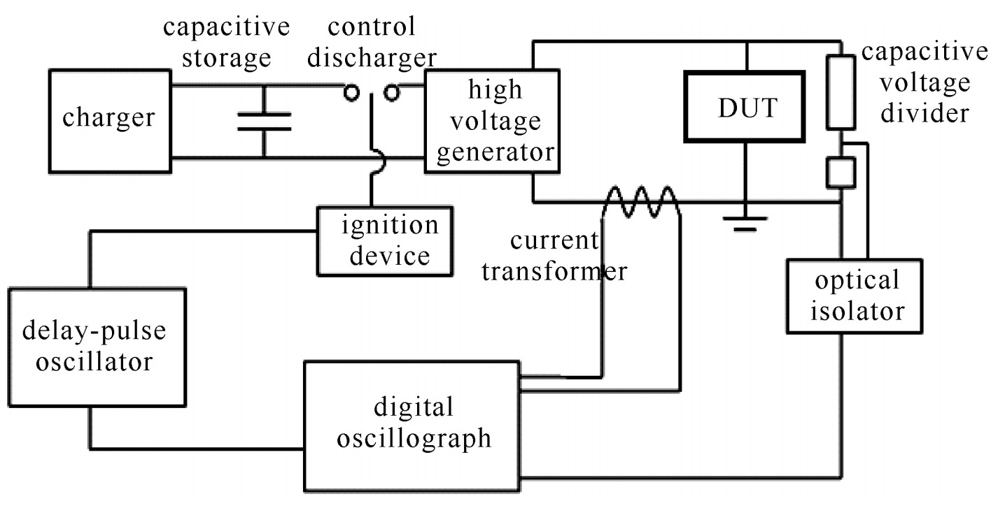
A block-diagram of the high-voltage pulse simulator is presented in Fig. 2. Basic elements of the simulator are: charger, capacitor store with controlled discharger, high-voltage generator, generator of delayed pulses (delayed-pulse oscillator), and ignition device.
A high-voltage pulse being formed by this simulator acts onto a device under test (DUT).Capacitive voltage divider, current transformer, optical isolator, as well as digital oscilloscope are used for measuring parameters of the simulated pulses. The charger is intended to charge the capacitive storage up to a certain voltage. By changing this voltage from 3 kV up to 20 kV, it is possible to change amplitude of a high-voltage pulse from 60 kV up to 400 kV.
After start of the controlled discharger the capacitor storage is discharging on the high-voltage generator, which forms a pulse with necessary parameters.
The generator of delayed pulses controls the work of the ignition device and starts the digital oscilloscope. Besides, it controls the work of the ignition system of the power line voltage simulator. Thus, a high-voltage pulse may be timed to occur at any point of waveform of a power line operating voltage.
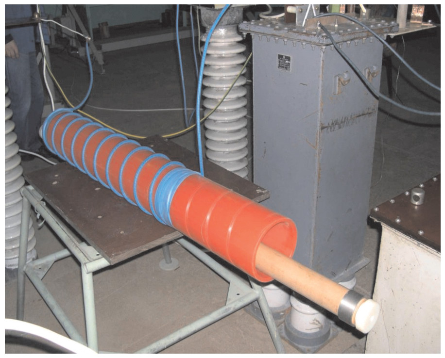
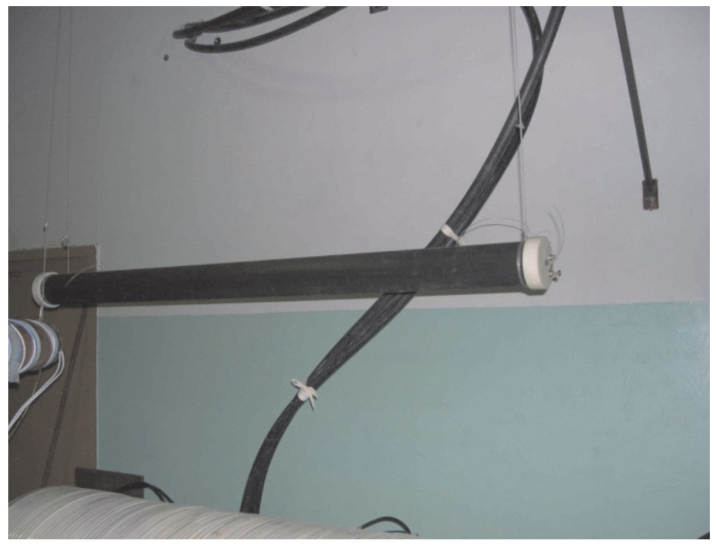
As a source of high-voltage pulses the generator based on exploding wires was used. This generator is shown in Fig. 3. It consists of the inductance and the block of exploding wires. Explosion of conductors occurs in the cylindrical chamber with a diameter of 60 mm and a length of 1550 mm. It was filled with nitrogen at pressure up to 1 MPa. Copper wires with a diameter of 40, 50 and 80 μm were used in experiments. Parameters of a generated pulse can be changed by means of changing the diameter and quantity of exploding wires.
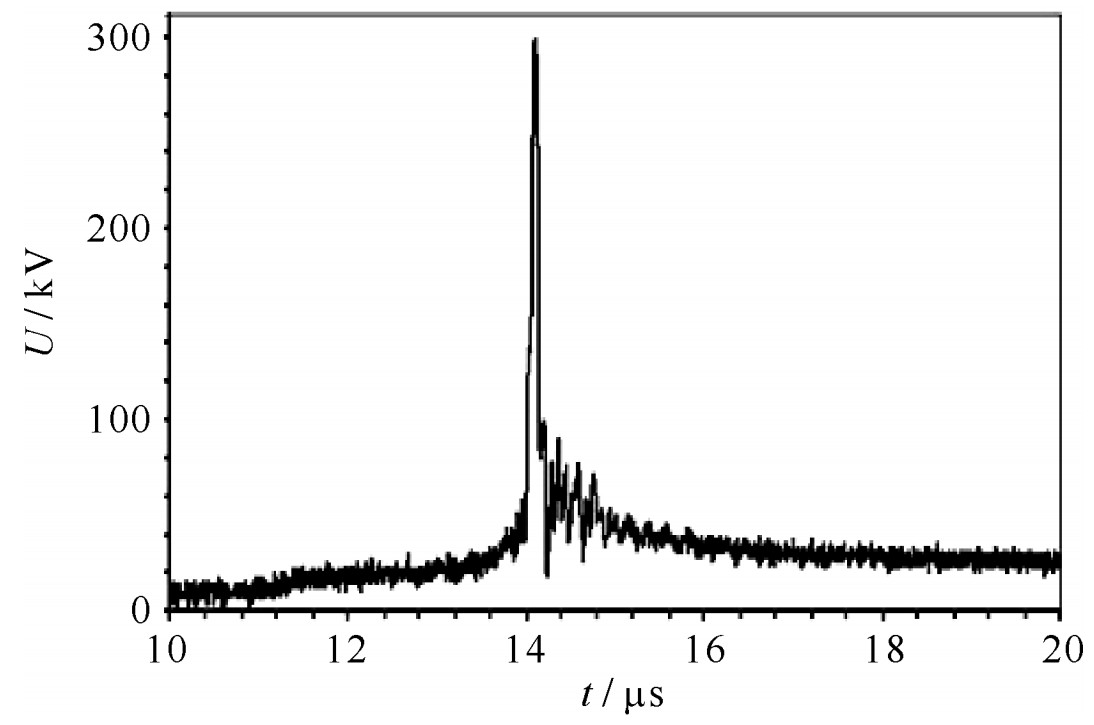
The generator based on exploding wires forms the pulse with the following parameters: peak voltage 60-400 kV; rise time 30-100 ns; pulse duration 50-500 ns. The waveform of generated pulse is shown in Fig. 4.
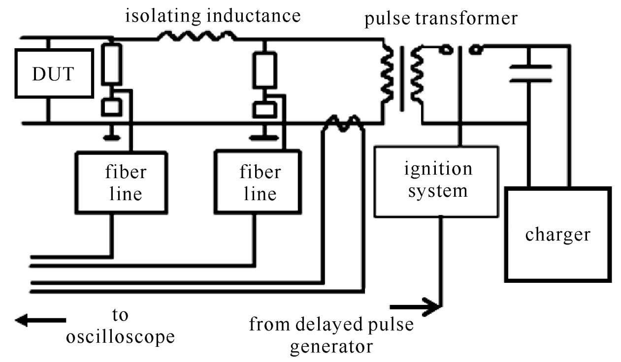
The block-diagram of the test equipment used to reproduce a power line operating voltage is shown in Fig. 5.
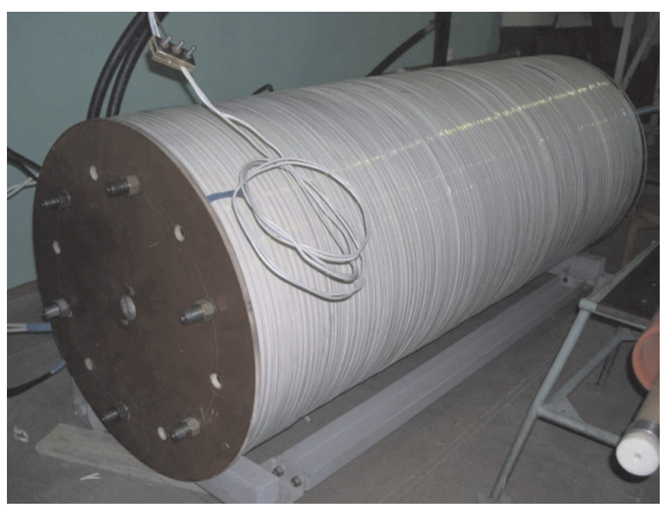
The basic element of the simulator of a power line operating voltage is the air-core pulse transformer. Fig. 6 shows the air-core transformer. It forms a voltage with an effective frequency from 30 Hz up to 100 Hz.
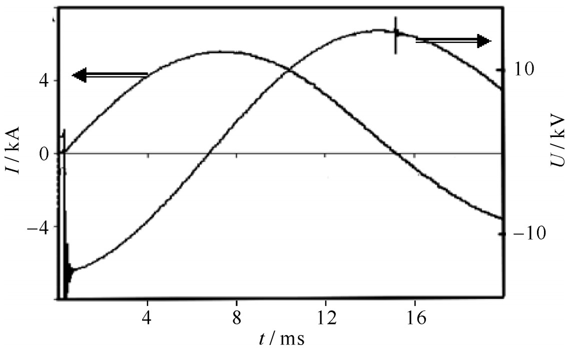
By changing the voltage of the capacitance storage one can control the amplitude of the reproduced power line operating voltage. Waveforms of a current in the primary winding of the air-core transformer and an open-circuit voltage in its secondary winding are presented in Fig. 7.
The open-circuit voltage of the transformer has an amplitude of 15 kV when the voltage of the charger is equal to 3 kV. The open-circuit voltage delays on 90° from the current in primary winding of the air-core transformer.
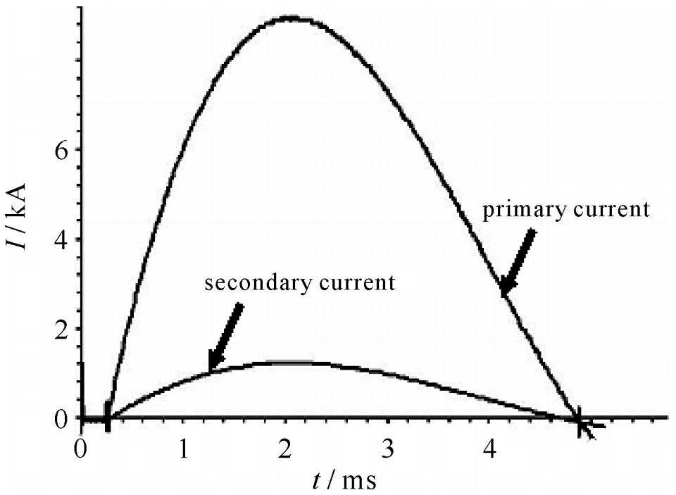
Required amplitude of the power line current may be reproduced in the secondary short-circuit winding. Waveforms of the current in the primary winding and the short-circuit current in the secondary winding are presented in Fig. 8. One can see that the current in the primary winding is about 10 kA. In this case the short-circuit current in the secondary winding is about 1 kA. This current will be a current of arc after overlapping of the DUT. Currents in the primary and secondary windings are in phase. Thus, the line operating voltage and the arc current will be 90° out of phase at power-on testing.
Control pulses of the delayed pulse generator start ignition systems of the high-voltage pulse simulator and the power line operating voltage simulator. Thus, time delay between the high-voltage pulse and maximum of the line operating voltage may be in range from several microseconds up to several milliseconds.
To measure parameters of the reproduced pulses and to register processes of DUT overlapping the following measuring tools are used:
— Digital oscilloscope;
— Digital camera (exposition time is 0.03 ms, shooting frequency is 300 Hz);
— Rogovski coil;
— Capacity divider (rise time 5 ns, factor of division 1∶350 000);
— Fiberoptic line;
— Resistive high-voltage divider.
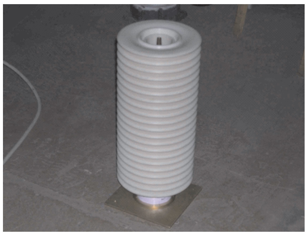
Photos of the resistive high-voltage divider and the capacity divider are presented in Fig. 9 and Fig. 10.
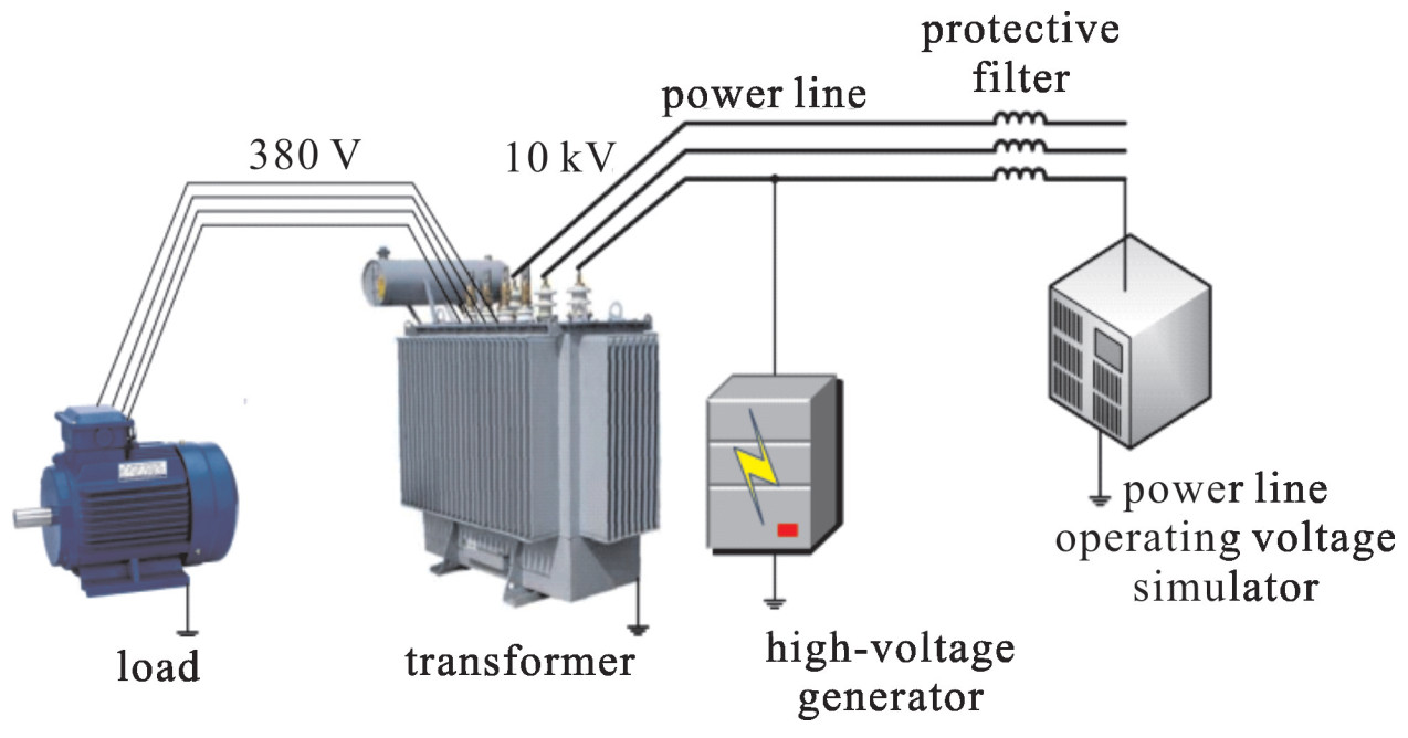
It is necessary to remind that the experimental setup described above has been used for high-voltage insulators tests. Naturally, the scheme of transformers tests should be different, as is shown in Fig. 11.
Apparently, this scheme does not need comments as it is analogous to the scheme of insulators tests described above. However, it should be noted that it has a shortcoming: only one phase is being exposed to influence of test pulses. The schemes overcoming this shortcoming are presented in the following section.
2. Transformer test methods using diesel-generator
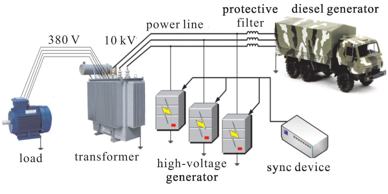
The first variant of the transformer test with the use of a serial 10 kV diesel-generator is shown in Fig. 12. Besides the diesel-generator, this scheme includes three high-voltage generators and a device for their synchronization.
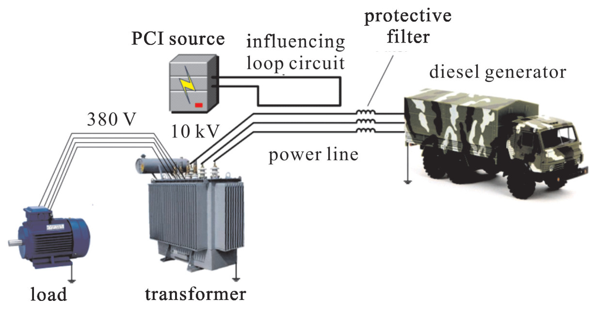
This scheme is much simpler in realization in comparison with the previous one, as it does not demand building of the simulator of an operating voltage for the high-voltage power line. However it has two shortcomings, one is that the extremely powerful high-voltage diesel-generator must be used, the other consists in using three synchronously functioning generators of high voltage pulses. It is possible to eliminate this difficulty by using the optimized scheme shown in Fig. 13.
Practical application of the optimized scheme shows that it is the simplest in realization in comparison with the other two of the three schemes. Yet it still has shortcomings. The main shortcoming is that the maximum voltage concerning the earth which can be induced by means of an influencing circuit does not exceed 100 kV.
3. Conclusions
The previous researches showed that joint action of a high-voltage pulse disturbance and an operating voltage of a power line leads to destruction of insulators of this line. This fact testifies about need of assessing immunity of other elements of power infrastructure to similar influences. A set of ways which can be used for test of high-voltage transformers is presented in the article. One of them is similar to the way used for test of insulators. It includes the high-voltage pulse simulating an electric disturbance and the pulse which simulates operating voltage of a power line being given to the transformer. The main shortcoming of this way is high cost of the simulator of the line operating voltage. For this reason, as a rule, only one phase of the transformer is being tested.
In the article two more ways of tests, free from this shortcoming, are offered. They allow applying the testing pulses to three phases simultaneously. A high-voltage pulse disturbance is simulated by means of three generators or by means of the loop circuit with a current which induces disturbances in all wires of the line simultaneously. An operating voltage of the line is simulated by means of the high power diesel-generator.
-
-
[1] Kozlov A, Louzganov S, Parfenov Y, et al. Research of power line insulators flashover at joint effect of high voltage disturbance and line operating voltage[C]//Proc 16th Int Zurich Symp EMC. 2005: 385-388. [2] Radasky W A. High power electromagnetic (HPEM) threats on smart grid[J]. IEEE Electromagnetic Compatibility Magazine, 2012, 1(2): 107-110. doi: 10.1109/MEMC.2012.6244984 [3] Parfenov Y V, Zdoukhov L N, Shurupov A V, et al. Research of flashover of power line insulators due to high-voltage pulses with power on and power off[J]. IEEE Trans Electromagnetic Compatibility, 2013, 55 (3): 467-474. doi: 10.1109/TEMC.2012.2236094 [4] North American Electric Corporation. High-impact, low-frequency event risk to the North American bulk power system[R/OL]. www.nerc.com. 期刊类型引用(1)
1. 秦锋,陈伟,王旭桐,任书庆,黄涛,聂鑫. 强电磁脉冲下金属氧化物避雷器瞬态响应特性. 高电压技术. 2022(08): 3326-3333 .  百度学术
百度学术其他类型引用(0)
-


 DownLoad:


 下载:
下载:
