

Hybrid control method to suppress neutral-point voltage fluctuation for three-phase three-level VIENNA rectifier
-
摘要: 针对三相三电平VIENNA整流器中点电位波动问题,建立了中点电流的数学模型,分析了中点波动形式、并结合中点电流数学模型分析了中点电位波动的根本原因,针对传统固定调节因子法抑制中点电位波动效果较差的缺点,提出了一种结合动态调节因子与电容偏差调节的混合抑制方法,给出了6扇区下偏差调节量和动态调节因子表达式,然后通过查表法将6扇区对应动态调节量注入到调制波中,实现了中点电位尤其三次基频波动的自动抑制,进一步修正后的混合抑制法还可有效抑制电容参数和负载不对称导致的中点大幅度波动,实验结果验证了策略的可行性和有效性。
-
关键词:
- 三相三电平VIENNA整流器 /
- 中点电位波动 /
- 混合抑制方法 /
- 动态调节因子
Abstract: Aiming at the problem of the third fundamental frequency fluctuation of the midpoint potential of VIENNA rectifier, the mathematical model of the midpoint current is established. The midpoint fluctuation form is analyzed, and the mathematical reason of midpoint fluctuation is pointed out by analysing the midpoint current mathematical model. To overcome the limitation of the traditional fixed adjustment factor control method to suppress neutral-point voltage fluctuation, a hybrid suppression method combining dynamic adjustment factor and capacitance deviation adjustment is proposed. This method realizes the automatic suppression of the midpoint potential fluctuation through looking for the tables for the deviation adjustment and the dynamic adjustment factor expression within the six sectors which is injected into the three-phase modulation waves, and further modified hybrid suppression method can effectively suppress the large fluctuation hybrid of the midpoint caused by asymmetry of the capacitance parameter and the unbalanced load. The experimental results verify the feasibility and validity of the strategy. -
VIENNA整流器是一种三相/三电平拓扑,输入电流正弦,可单位功率因数运行,输出电压可控,并因其开关数量少、应力小、无死区等优点成为当今整流器领域的一个研究热点[1-4]。然而三电平拓扑存在中点波动问题,它会导致功率器件承受电压不均等,甚至导致器件过压损坏,还会影响线电压波形,导致电流总谐波畸变率(Total Harmonic Distortion, THD)增大,这些问题严重影响包括VIENNA整流器在内的三电平拓扑的推广与应用,因此必需解决。
目前国内外学者在三电平拓扑中点问题方面已开展了大量研究[5-7],解决方法大致可归结为三类:(1)基于P,N小矢量调节方法[5];(2)基于零序分量注入调节方法[6];(3)中点电位偏差前馈法[7]。其中,文献[8]根据P,N小矢量对中点的相反作用原理,采取类似于滞环方法抑制中点波动,但此P,N小矢量法依赖于复杂的三电平调制策略;文献[9]采用零序分量注入法来平衡中点的波动,但零序分量的计算较为复杂;文献[10]利用SPWM注入零序分量的方式解决中点电压波动,算法的复杂性相对较低;文献[11]采用一种中点电位偏差前馈补偿法,为固定调节因子算法,其比例调节因子的选取依靠工程经验,缺少理论依据,且难以抑制中点的三次基频波动。
为有效解决VIENNA整流器的三次基频中点波动,本文提出了一种结合动态调节因子与电容偏差调节的混合中点抑制方法,其中改进型混合抑制方法还可有效抑制电容参数和负载不对称导致的中点大幅度波动。
1. VIENNA整流器中点数学模型
1.1 中点电流的数学模型
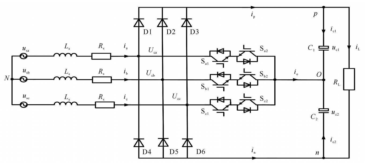
VIENNA整流器拓扑如图 1所示,对VIENNA整流器拓扑电路进行分析,可知两电容的电压表达式为
{Vcl=1C1∫t0ic1dt+Vc10Vc2=1C2∫t0ic2dt+Vc20 (1) 式中:ic1,ic2为C1,C2的充放电电流;Vc10和Vc20为C1,C2的初始电压。
从式(1)可以看出电容电压与电容电压初始值以及电容实时充放电电流有关。为便于分析,建立中点电流数学模型,假设直流侧输出电压恒定;输入电流、调制波均为三相对称正弦量;功率器件不考虑开关延时等非线性因素。
定义开关函数表达式sxo为
sxo={0,(sxo 开通 )1,(sxo 关断, usx>0;x=a,b,c)−1,(sxo 关断, usx<0) (2) 根据图 1所示拓扑结构,根据基尔霍夫电流定律,中点电流的表达式如下
{io=−(ic1+ic2)=C2duc2 dt−C1duc1 dtio=saoia+sboib+scoic (3) 由中点电流的表达式(3)知:中点电流是以不为零的高频形式存在,高频的中点电流源于直流侧电容的充放电,这是导致中点电位波动的根本原因。
1.2 中点电流的三次基频波动
用高频开关函数中的基波函数(调制波)代替高频开关函数,可以得到中点电流的基波模型如下
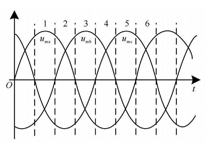
{io=(duc2 dt−duc1 dt)Cio=(1−|uma|)ia+(1−|umb|)ib+(1−|umc|)ic (4) 为寻求中点电流在一个工频周期内的变化规律,获得每个扇区中点电流的数学表达式,将一个周期内的输入电压(图 2中uma,umb,umc)分成如图 2所示的6个扇区,对每个扇区的中点电流表达式进行分析。
以第一扇区为例,显然uma>0,umb < 0,umc < 0,则第一扇区内中点电流的基频表达式为
io=(1−uma)ia+(1+umb)ib+(1+umc)ic (5) 三相平衡系统中,三相电流之和为零,存在如下关系
{io=−umaia+umbib+umcicuma+umb+umc=0 (6) 在闭环控制下,系统稳态时电压电流同相位,电流瞬时值可用瞬时电压乘上比例系数表示为
ix=kumx(x=a,b,c;k>0) (7) 式中:k为电流幅值与电压指令幅值之比。
联合式(6),(7)可得
io=−2kumbumc,io<0 (8) 式(8)表明,第一扇区内中点电流基波分量小于零,此时直流侧电容C1充电,C2放电,整个扇区内Uc1 < Uc2;并且可知中点电流呈正弦规律脉动。同理,其他5个扇区内中点电流的表达式及电容的充放电情况如表 1所示。
表 1 各扇区内中点电流及其对中点电位的影响Table 1. Neutral point current expressions in each sector and its effects on neutral pointsector No. neutral point current expression capacitor voltage 1 io=-2kumbumc < 0 C1↑ C2↓,C1>C2 2 io=-2kumbuma < 0 C1↓ C2↑,C1 < C2 3 io=-2kumaumc < 0 C1↑ C2↓,C1>C2 4 io=-2kumbumc < 0 C1↓ C2↑,C1 < C2 5 io=-2kumbuma < 0 C1↑ C2↓,C1>C2 6 io=-2kumaumc < 0 C1↓ C2↑,C1 < C2 2. 中点电位混合抑制方法
2.1 中点电位偏差前馈补偿法
中点电位偏差前馈补偿法是一种简单实用的中点平衡控制方法,其将中点电压偏差通过比例系数md放大后叠加到参考电压上,用以减小中点电流的幅值,从而使中点电位趋于平衡。定义直流侧中点电位偏移量为
Δuc=Uc2−Uc1 (9) 同样以第一扇区为例,引入中点电位偏差控制后,其中点电流的表达式为
io′=(1−uma−mdΔuc)ia+(1+umb+mdΔuc)ib+(1+umc+mdΔuc)ic (10) 化简得
io′=io−2mdkumaΔuc (11) 从式(11)知:引入中点电位偏差控制后中点电流基波表达式多了一项,这一项的存在使得控制后的中点电流幅值减小,进而减小了电容充放电电流,最终抑制了直流侧电容电压不平衡。
由前面分析可知,中点电位波动的本质原因是中点电流的基波分量(忽略含量较低的高频谐波电流)不为零。因此,假设式(11)恒等于零,此时中点电流基波分量恒为零,理论上可消除中点偏移问题,联立式(8)可得
md=−umbumcumaΔuc (12) 式(12)为中点电位调节因子,结合式(9),可获得中点电压偏差动态调节量,其表达式如式(13)所示
umd=mdΔuc=−umbumcuma (13) 同理可获得其他扇区的中点电位调节因子和中点电压偏差调节量表达式,如表 2所示。
表 2 各扇区内调节因子和调节量表达式Table 2. Regulation factor expression in each sectorsector No. neutral-point voltage adjustment factor md neutral-point deviation adjustment umd influence on neutral-point current influence on the neutral-point voltage fluctuation 1,4 $-\frac{u_{\mathrm{mb}} u_{\mathrm{mc}}}{u_{\mathrm{ma}} \mathit{\Delta}_{\mathrm{uc}}} $ $-\frac{u_{\mathrm{mb}} u_{\mathrm{mc}}}{u_{\mathrm{ma}}} $ reduced reduced 2,5 $-\frac{u_{\mathrm{mb}} u_{\mathrm{ma}}}{u_{\mathrm{mc}} \mathit{\Delta}_{\mathrm{uc}}} $ $ -\frac{u_{\mathrm{mb}} u_{\mathrm{ma}}}{u_{\mathrm{mc}}}$ reduced reduced 3,6 $ -\frac{u_{\mathrm{ma}} u_{\mathrm{mc}}}{u_{\mathrm{mb}} \mathit{\Delta}_{\mathrm{uc}}}$ $ -\frac{u_{\mathrm{ma}} u_{\mathrm{mc}}}{u_{\mathrm{mb}}}$ reduced reduced 2.2 结合动态调节因子与电容偏差的混合中点电位平衡控制法
根据式(12),若io恒为零,则直流侧电容无电压偏差,即要求传统固定调节因子的取值接近无穷大,即
limΔuc→0(md=−umbumcumaΔuc)=+∞ (14) 式(14)表明中点电流恒为零,比例系数md就要无穷大,这是无法实现的;也就是说采用传统的固定调节因子算法抑制中点偏移依赖于中点本身的偏差,此中点平衡控制方法下中点偏差不能被完全消除,抑制中点电位波动能力有限。为消除中点波动影响,采用了一种联合动态调节因子与电容偏差的混合抑制方法。
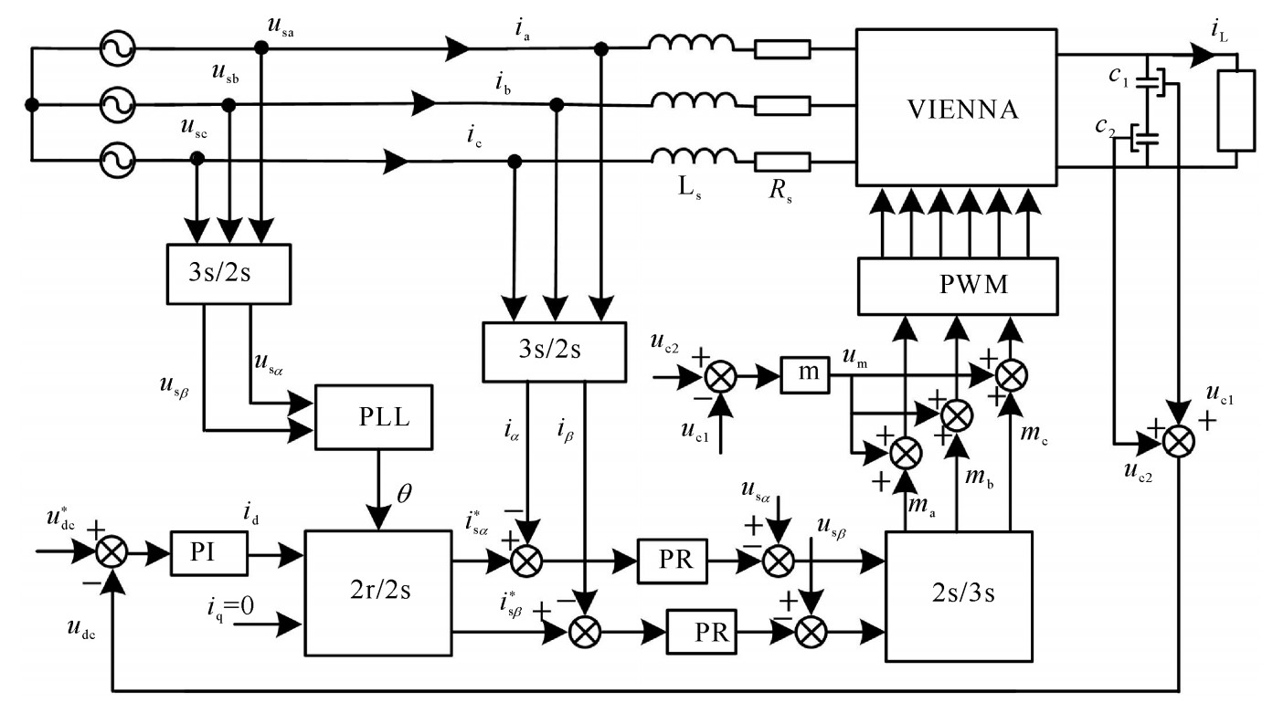
图 3所示为基于双闭环控制系统的动态调节因子与电容偏差结合的混合中点控制框图,设叠加在调制波上的补偿量为um,由两部分组成,第一部分为实际中点电位的偏差,第二部分为动态调节因子组成的调节量,两者组成:
um=um0+umd (15)  图 3 基于双闭环控制系统的中点电位混合控制方法框图Figure 3. Block diagram of dual closed loop control system based on dynamic regulation factor
式中:um0为偏差调节量;umd为动态因子调节量。
在第一扇区内,动态因子调节量为
umd=mdΔuc=−umbumcuma (16) 如不考虑电容参数不对称和负载不平衡的影响,则
Δuc=um0 (17) 联合(15)~(17)式可得
{um=Δuc−umbumcuma=Δuc(1−umbumcumaΔuc)k2=1−umbumcumaΔuc (18) 式(18)中,k2为动态调节因子,这样就用动态调节因子代替了原来的固定调节因子,实现了中点电位的动态调节,具有更好的中点平衡控制效果,具有适应性强的特点。同理,结合表 2可得到其他扇区的中点电位调节量,如表 3所示。
表 3 中点电位动态调节因子和调节量表达式Table 3. Neutral voltage dynamic regulation quantity expressionsector No. dynamic adjustment factor k2 dynamic adjustment um 1,4 $1-\frac{u_{\mathrm{mb}} u_{\mathrm{mc}}}{u_{\mathrm{ma}} \mathit{\Delta}_{\mathrm{uc}}} $ $ \mathit{\Delta}_{\mathrm{uc}}-\frac{u_{\mathrm{mb}} u_{\mathrm{m} \mathrm{c}}}{u_{\mathrm{ma}}}$ 2,5 $1-\frac{u_{\mathrm{mb}} u_{\mathrm{ma}}}{u_{\mathrm{mc}} \mathit{\Delta}_{\mathrm{uc}}} $ $\mathit{\Delta}_{\mathrm{uc}}-\frac{u_{\mathrm{mb}} u_{\mathrm{ma}}}{u_{\mathrm{mc}}} $ 3,6 $1-\frac{u_{\mathrm{mc}} u_{\text {ma }}}{u_{\mathrm{mb}} \mathit{\Delta}_{\mathrm{uc}}} $ $\mathit{\Delta}_{\mathrm{uc}}-\frac{u_{\mathrm{mc}} u_{\mathrm{ma}}}{u_{\mathrm{mb}}} $ 在一些特殊工况下,如电容参数不对称或者直流侧负载不平衡,会引起中点大幅度波动,需进一步抑制,只需在式(17)中引入调节系数k1就能达到抑制此类不平衡引起的中点波动效果,则um0表达式为
um0=k1Δuc (19) 式(18)也变为式(20),其他扇区结果类似,不再赘述。
{um=Δuc(k1−umbumcumaΔuc)k2=k1−umbumcumaΔuc (20) 3. 实验结果
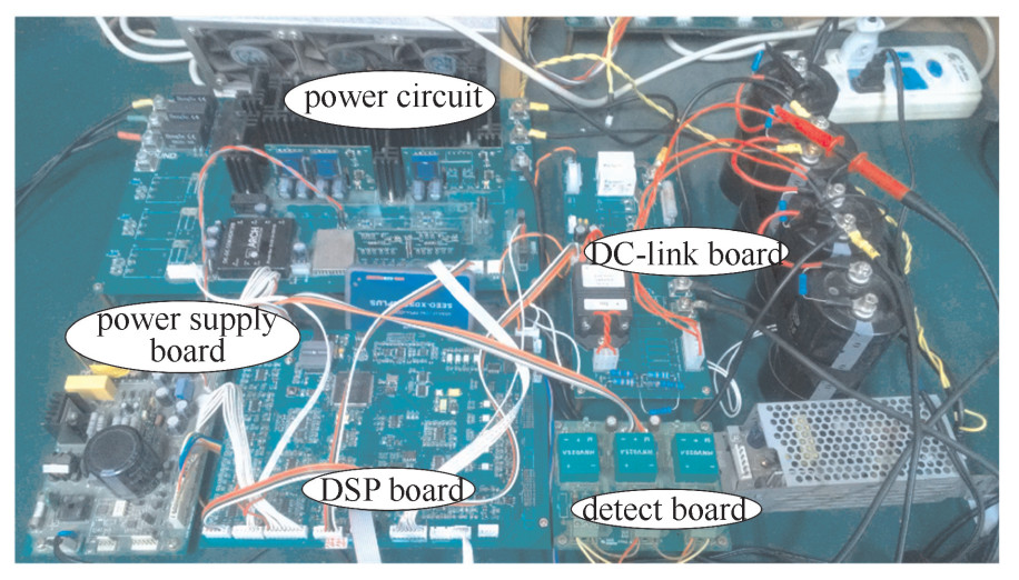
为了验证算法的可行性,基于DSP2812搭建了一台VIENNA整流器实验样机,如图 4所示,参数如表 4所示。
表 4 系统实验参数Table 4. Parameters for system experimentgrid side line to line voltage/V DC side voltage/V load /Ω switching frequency /kHz filter inductor / H filter capacitor /μF 100 200 180~120 5 5 1600 3.1 正常工况下中点平衡控制验证
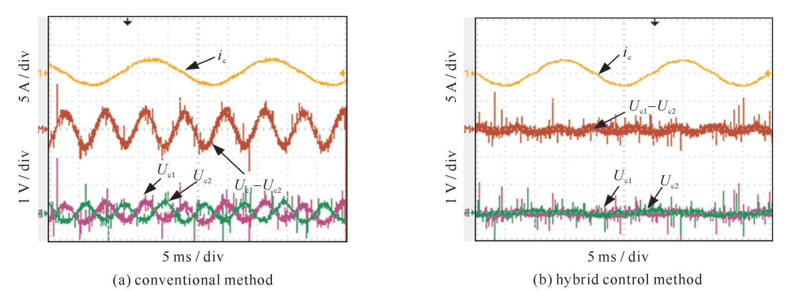
图 5为固定调节因子传统方法与动态调节因子的混合方法下的直流侧电容﹑电容偏差和输入电流波形,由波形对比知,传统固定调节因子中点控制算法下两电容压差含三次基频分量约为±0.75 V,两电容幅值不等;在混合抑制法下,两电容压差三次基频分量控制到±0.15 V以内,两电容电压基本相等。验证了文中结合动态调节因子与电容偏移量的混合中点平衡控制法的有效性。
 图 5 传统固定调节因子与混合中点控制法对比波形Figure 5. Waveforms of different neutral point control methods
3.2 特殊工况下中点平衡控制验证
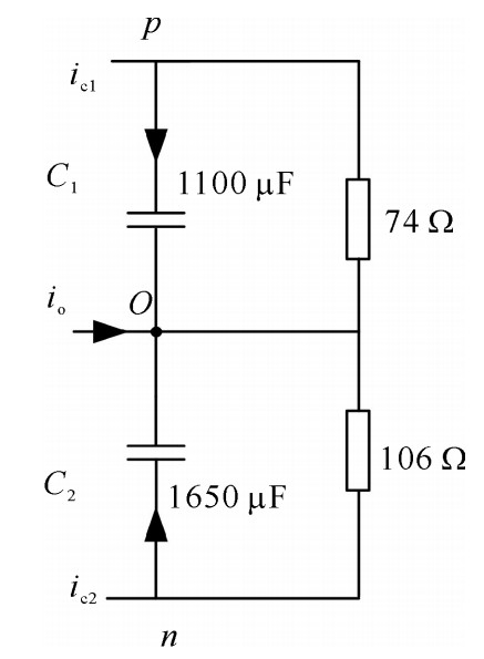
电容制造工艺的差异或长时间使用疲乏后充放电特性不一致都会导致电容参数变化。实验中采用两个不同厂家不同容值电容(CEB 2200 μF/400 V两个串联成C1;江海公司3300 μF/450 V两个串联组成C2)模拟电容参数不一致。在某些需要正负电源的场合会出现两个电源负载不相同的情况,实验中采用两个负载电阻分别为R1为74 Ω,R2为106 Ω模型此负载不平衡工况,直流侧等效电路图如图 6所示。
 图 6 电容参数和负载不一致时直流侧等效电路Figure 6. Equivalent DC side circuit under asymmetric capacitance and unbalanced load
如图 7所示为特殊工况下传统固定调节因子算法和改进后混合中点控制法对比波形。图 7(a),(b)中所示为稳态时两种中点抑制算法下的电容电压﹑电容偏差和输入电流波形,从图中可以看出传统控制算法下中点电位不仅有三次基频波动而且存在直流偏移,改进的中点电位控制算法下波形仅存在直流偏差量,补偿了由负载和电容不对称导致的中点电位偏移,并使中点趋于平衡。图 7(c),(d)为直流侧电容电压交流含量﹑两电容偏差交流含量和输入电流波形,波形对比知,传统算法对于三次基频波动抑制效果欠佳,改进后的算法基本消除了中点的三次基频波动。
 图 7 传统固定因子算法和改进后混合中点控制法对比波形Figure 7. Waveforms of different neutral point control methods
4. 结论
针对VIENNA整流器等三电平拓扑的中点不平衡共性问题,研究了一种结合动态调节因子与电容偏差调节的混合中点平衡控制方法,这种方法能够有效降低中点电位的三次基频波动,同时能够对直流偏差进行有效地抑制,有效削弱了中点电位波动,进一步修正后的混合抑制方法还可有效抑制电容参数不一致和负载不平衡导致的中点电位大幅度波动。中点平衡控制方法对输入电流THD的影响一直是评判中点平衡控制方法性能的一项重要指标,本文所提出方法对输入电流THD的影响在此文中并没有进行深入探讨,这将是今后本课题组的一个重要研究方向。
-

图 3 基于双闭环控制系统的中点电位混合控制方法框图
Figure 3. Block diagram of dual closed loop control system based on dynamic regulation factor

图 5 传统固定调节因子与混合中点控制法对比波形
Figure 5. Waveforms of different neutral point control methods

图 6 电容参数和负载不一致时直流侧等效电路
Figure 6. Equivalent DC side circuit under asymmetric capacitance and unbalanced load
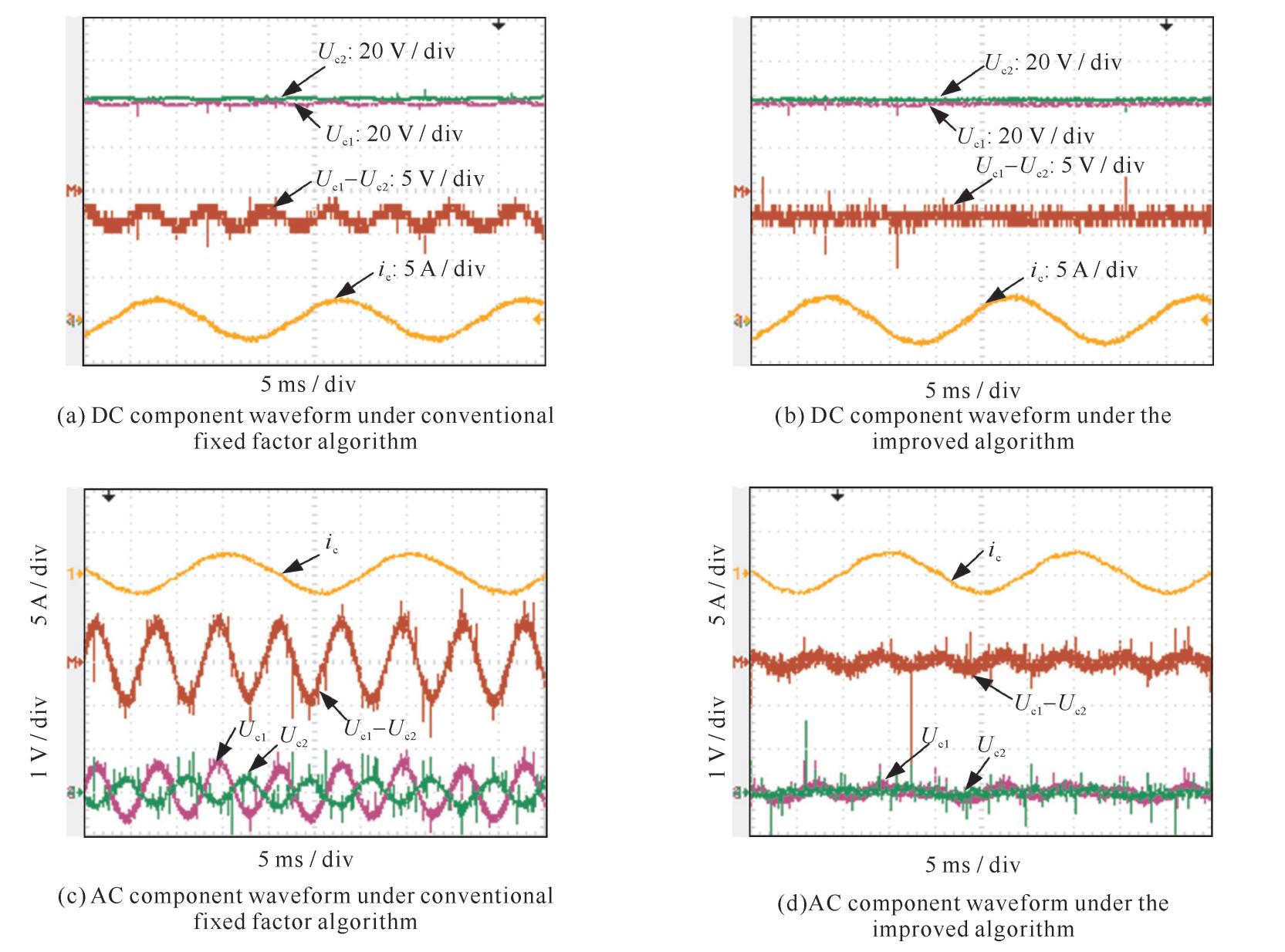
图 7 传统固定因子算法和改进后混合中点控制法对比波形
Figure 7. Waveforms of different neutral point control methods
表 1 各扇区内中点电流及其对中点电位的影响
Table 1. Neutral point current expressions in each sector and its effects on neutral point
sector No. neutral point current expression capacitor voltage 1 io=-2kumbumc < 0 C1↑ C2↓,C1>C2 2 io=-2kumbuma < 0 C1↓ C2↑,C1 < C2 3 io=-2kumaumc < 0 C1↑ C2↓,C1>C2 4 io=-2kumbumc < 0 C1↓ C2↑,C1 < C2 5 io=-2kumbuma < 0 C1↑ C2↓,C1>C2 6 io=-2kumaumc < 0 C1↓ C2↑,C1 < C2  下载: 导出CSV
表 2 各扇区内调节因子和调节量表达式
Table 2. Regulation factor expression in each sector
sector No. neutral-point voltage adjustment factor md neutral-point deviation adjustment umd influence on neutral-point current influence on the neutral-point voltage fluctuation 1,4 $-\frac{u_{\mathrm{mb}} u_{\mathrm{mc}}}{u_{\mathrm{ma}} \mathit{\Delta}_{\mathrm{uc}}} $ $-\frac{u_{\mathrm{mb}} u_{\mathrm{mc}}}{u_{\mathrm{ma}}} $ reduced reduced 2,5 $-\frac{u_{\mathrm{mb}} u_{\mathrm{ma}}}{u_{\mathrm{mc}} \mathit{\Delta}_{\mathrm{uc}}} $ $ -\frac{u_{\mathrm{mb}} u_{\mathrm{ma}}}{u_{\mathrm{mc}}}$ reduced reduced 3,6 $ -\frac{u_{\mathrm{ma}} u_{\mathrm{mc}}}{u_{\mathrm{mb}} \mathit{\Delta}_{\mathrm{uc}}}$ $ -\frac{u_{\mathrm{ma}} u_{\mathrm{mc}}}{u_{\mathrm{mb}}}$ reduced reduced
下载: 导出CSV
表 3 中点电位动态调节因子和调节量表达式
Table 3. Neutral voltage dynamic regulation quantity expression
sector No. dynamic adjustment factor k2 dynamic adjustment um 1,4 $1-\frac{u_{\mathrm{mb}} u_{\mathrm{mc}}}{u_{\mathrm{ma}} \mathit{\Delta}_{\mathrm{uc}}} $ $ \mathit{\Delta}_{\mathrm{uc}}-\frac{u_{\mathrm{mb}} u_{\mathrm{m} \mathrm{c}}}{u_{\mathrm{ma}}}$ 2,5 $1-\frac{u_{\mathrm{mb}} u_{\mathrm{ma}}}{u_{\mathrm{mc}} \mathit{\Delta}_{\mathrm{uc}}} $ $\mathit{\Delta}_{\mathrm{uc}}-\frac{u_{\mathrm{mb}} u_{\mathrm{ma}}}{u_{\mathrm{mc}}} $ 3,6 $1-\frac{u_{\mathrm{mc}} u_{\text {ma }}}{u_{\mathrm{mb}} \mathit{\Delta}_{\mathrm{uc}}} $ $\mathit{\Delta}_{\mathrm{uc}}-\frac{u_{\mathrm{mc}} u_{\mathrm{ma}}}{u_{\mathrm{mb}}} $
下载: 导出CSV
表 4 系统实验参数
Table 4. Parameters for system experiment
grid side line to line voltage/V DC side voltage/V load /Ω switching frequency /kHz filter inductor / H filter capacitor /μF 100 200 180~120 5 5 1600
下载: 导出CSV
-
[1] Kolar J W, Zach F C. A novel three-phase three-switch three-level PWM rectifier[C]//IEEE 1994 International Conference on Power Conversion. 1994: 125-138 [2] 申兴, 王久和. 分段式三电平Vienna整流器中性点电位平衡控制策略研究[J]. 电气工程学报, 2016, 11(10): 31-36. https://www.cnki.com.cn/Article/CJFDTOTAL-DQZH201610006.htmShen Xing, Wang Jiuhe. A study on the balance control strategy of neutral point potential in the third level of Vienna rectifier. Journal of Electrical Engineering, 2016, 11(10): 31-36 https://www.cnki.com.cn/Article/CJFDTOTAL-DQZH201610006.htm [3] Lee J S, Lee K B. Performance analysis of carrier-based discontinuous PWM method for Vienna rectifiers with neutral-point voltage balance[J]. IEEE Trans Power Electronics, 2016: 4075-4084. [4] Adhikari J, Prasanna I V, Panda S K. Reduction of input current harmonic distortions and balancing of output voltages of the vienna rectifier under supply voltage disturbances[J]. IEEE Trans Power Electronics, 2017, 32(7): 5802-5812. doi: 10.1109/TPEL.2016.2611059 [5] 桂石翁, 吴芳, 万山明, 等. 变虚拟空间矢量的三电平NPC变换器中点电位平衡控制策略[J]. 中国电机工程学报, 2015, 35(19): 5013-5021. https://www.cnki.com.cn/Article/CJFDTOTAL-ZGDC201519021.htmGui Shiweng, Wu Fang, Wan Shanming, et al. Control strategy of the neutral voltage balance control in the three-level NPC converter of virtual space vector. Proceedings of the CSEE, 2015, 35(19): 5013-5021 https://www.cnki.com.cn/Article/CJFDTOTAL-ZGDC201519021.htm [6] 谢路耀, 金新民, 吴学智, 等. 基于零序电压注入与调制波分解的三电平脉宽调制策略[J]. 电工技术学报, 2014, 29(10): 27-37. https://www.cnki.com.cn/Article/CJFDTOTAL-DGJS201410004.htmXie luyao, Jin Xinmin, Wu Xuezhi, et al. Three levels of pulse width modulation strategy based on zero-sequence voltage injection and modulation wave decomposition [J]. Journal of Electrical Technology, 2014, 29(10): 27-37 https://www.cnki.com.cn/Article/CJFDTOTAL-DGJS201410004.htm [7] 王小峰, 邓焰, 何湘宁. 三相三电平二极管箝位型整流器的单载波调制和中点平衡控制策略[J]. 中国电机工程学报, 2006, 26(8): 7-11. https://www.cnki.com.cn/Article/CJFDTOTAL-ZGDC200608001.htmWang Xiaofeng, Deng Yan, He Xiangning. Single-carrier modulation and midpoint balancing method for simplified three-phase three-level diode-clamped rectifier. Proceedings of the CSEE, 2006, 26(8): 7-11 https://www.cnki.com.cn/Article/CJFDTOTAL-ZGDC200608001.htm [8] 王正, 谭国俊, 曾维俊, 等. 基于SVPWM的VIENNA整流器研究[J]. 电气传动, 2011, 41(4): 31-34. https://www.cnki.com.cn/Article/CJFDTOTAL-DQCZ201104008.htmWang Zheng, Tan Guojun, Zeng Weijun, et al. Research on VIENNA rectifier based on SVPWM. Electric Drive, 2011, 41(4): 31-34 https://www.cnki.com.cn/Article/CJFDTOTAL-DQCZ201104008.htm [9] 王正, 谭国俊, 曾维俊, 等. 基于SVPWM的VIENNA整流器研究[J]. 电气传动, 2011, 41(4): 31-34. https://www.cnki.com.cn/Article/CJFDTOTAL-DQCZ201104008.htmWang Zheng, Tan Guojun, Zeng Weijun, et al. Research on VIENNA rectifier based on SVPWM. Electric Drive, 2011, 41(4): 31-34 https://www.cnki.com.cn/Article/CJFDTOTAL-DQCZ201104008.htm [10] 王新宇, 何英杰, 刘进军. 注入零序分量SPWM调制三电平逆变器直流侧中点电压平衡控制机理[J]. 电工技术学报, 2011, 26(5): 70-77. https://www.cnki.com.cn/Article/CJFDTOTAL-DGJS201105012.htmWang Xinyu, He Yingjie, Liu Jinjun. Injection zero sequence component SPWM modulation three-level inverter DC side midpoint voltage balance control mechanism. Transactions of China Electrotechnical Society, 2011, 26(5): 70-77 https://www.cnki.com.cn/Article/CJFDTOTAL-DGJS201105012.htm [11] 宋卫章, 黄骏, 钟彦儒, 等. 带中点电位平衡的Vienna整流器滞环电流控制方法[J]. 电网技术, 2013, 37(7): 1909-1914 https://www.cnki.com.cn/Article/CJFDTOTAL-DWJS201307019.htmSong Weizhang, Huang Jun, Zhong Yanru, et al. Hysteresis current control method of Vienna rectifier with neutral-point potential balance. Power System Technology, 2013, 37(7): 1909-1914 https://www.cnki.com.cn/Article/CJFDTOTAL-DWJS201307019.htm -


 下载:
下载:


 点击查看大图
计量
- 文章访问数: 1481
- HTML全文浏览量: 595
- PDF下载量: 129
- 被引次数: 0
