Influence of armature-rail contact surface morphology on starting characteristics of armature
-
摘要:
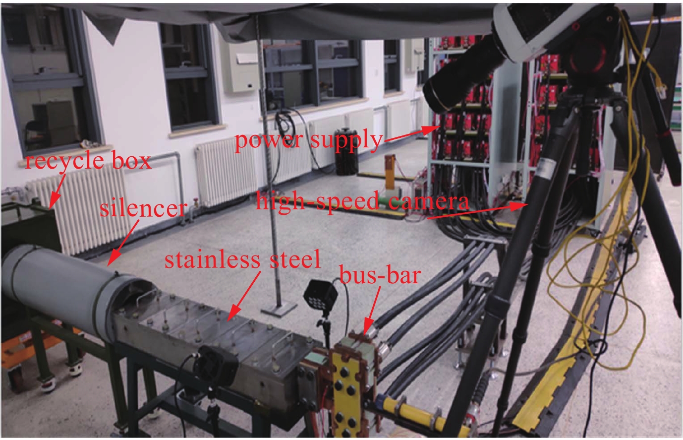
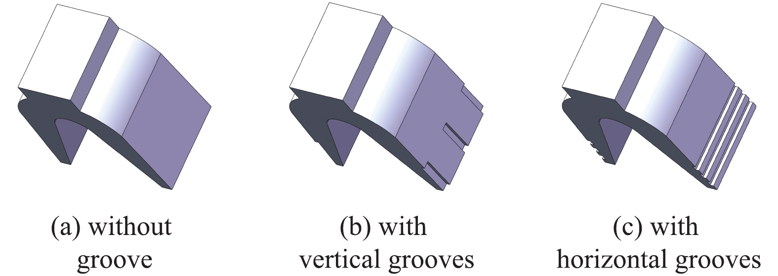
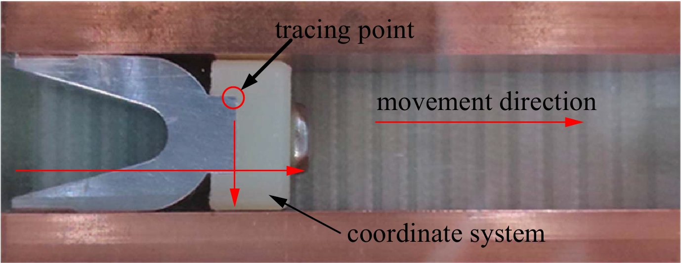
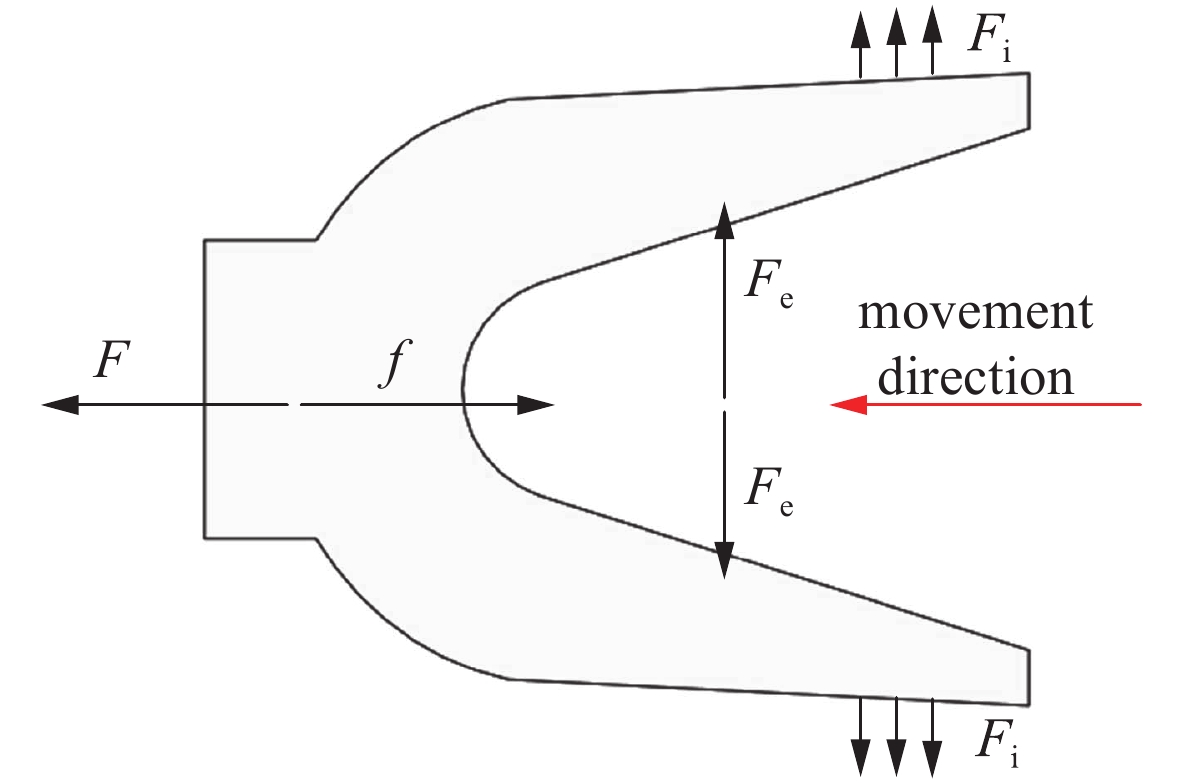
在脉冲大电流直线驱动装置中,电枢和轨道的接触状态会改变电枢起动特性,而电枢起动过程将直接影响整个发射系统的效率和寿命,因此有必要对电枢起始阶段的滑动接触状态进行研究。搭建发射实验平台,通过高速相机观察电枢起动状态,并结合有限元软件 ANSYS,对电枢的预紧力、初始接触状态以及电磁压力、电流密度进行仿真分析,研究电枢表面形貌对电枢起动的影响。结论表明:开槽电枢增加了电枢本身的柔顺性,使得预紧力增大,同时由于电流趋肤效应使得电流密度分布更加均匀,从而电磁压力增大,电枢起动变慢,接触电阻变小。实验和仿真结果对于改善电枢起动过程的接触状态,减轻烧蚀具有重要意义。
Abstract:The armature-rail contact interface affects the characteristics of armature startup in the pulsed high current linear driver. Furthermore, the armature startup has an influence on the system efficiency and lifetime. This paper discusses the effect of armature surface morphology on armature startup. In the experiments, a high-speed camera was set up to observe the armature startup. Combined with the finite element software ANSYS, the pre-tightening force and contact status were simulated. Besides, the electromagnetic pressure and current density were also obtained by simulation. The results show that groove increased the flexibility of armature and the homogeneity of current distribution was improved by the current skin effect. Owing to the increasing pressure, the groove armature startup was delayed and its contact resistance reduced. The results have important significance to improve contact condition and reduce erosion.
-
表 1 电枢起动时刻
Table 1. Startup time of armature
experiment
No.startup time/μs no groove vertical groove horizontal groove 1 125 162.5 175 2 150 175 187 3 162.5 180 190 表 2 仿真模型中的主要参数
Table 2. Main parameters of material for simulation
ρ/(kg·m−3) E/Pa v δs rail 8 830 1.1×10¹¹ 0.34 4.0×10⁸ armature 2 770 7.1×10¹⁰ 0.33 2.8×10⁸ 表 3 计算结果
Table 3. Calculation results
armature structure armature startup time/μs the pre-tightening force/N electromagnetic pressure/N FN/N with out groove 125 1 324.4 508 1 832.4 with vertical grooves 162.5 1 373.1 566 1 939.1 with horizontal grooves 175 1 403.1 658 2 061.1 -
[1] Marshall R A, Ying W. Railguns: their science and technology[M]. Beijing: China Machine Press, 2004: 4-5. [2] Hsieh K T, Kim B K. 3D modeling of sliding electrical contact[J]. IEEE Trans Magn, 1997, 33(1): 237-239. [3] Schneider M, Woetzel M, Wenning W, et al. The ISL rapid fire railgun project RAFIRA—Part Ⅰ: Technical aspects and design considerations[J]. IEEE Trans Magn, 2009, 45(1): 442-447. doi: 10.1109/TMAG.2008.2008468 [4] Barber J P, Dreizin Y A. Model of contact transitioning with realistic armature-rail interface[J]. IEEE Trans Magn, 1995, 31(1): 96-100. doi: 10.1109/20.364721 [5] Barber J P, Challita A, Mass B, et al. Contact transition in metal armatures railguns[J]. IEEE Trans Magn, 1991, 27(1): 228-232. doi: 10.1109/20.101031 [6] Watt T, Stefani F, Crawford M, et al. Investigation of damage to solid-armature railguns at startup[J]. IEEE Trans Magn, 2007, 43(1): 214-218. doi: 10.1109/TMAG.2006.887432 [7] 朱仁贵, 李治源, 张倩, 等. 电磁发射枢轨界面初始接触状态研究[J]. 强激光与粒子束, 2014, 26:115003. (Zhu Rengui, Li Zhiyuan, Zhang Qian, et al. Initial contact status for interface between armature and rail in electromagnetic launch. High Power Laser and Particle Beams, 2014, 26: 115003 [8] 徐伟东, 袁伟群, 陈允, 等. 电磁轨道发射器连续发射的滑动电接触[J]. 强激光与粒子束, 2012, 24(3):668-672. (Xu Weidong, Yuan Weiqun, Chen Yun, et al. Sliding electrical contact performance of electromagnetic launcher system in rapid fire mode. High Power Laser and Particle Beams, 2012, 24(3): 668-672 [9] 陈允, 徐伟东, 袁伟群, 等. 电磁发射中铝电枢与不同材料导轨间的滑动电接触特性[J]. 高电压技术, 2013, 39(4):937-942. (Chen Yun, Xu Weidong, Yuan Weiqun, et al. Sliding electrical contacts between aluminum armature and different material rails in railgun. High Voltage Engineering, 2013, 39(4): 937-942 doi: 10.3969/j.issn.1003-6520.2013.04.025 [10] Schneider M, Eckenfels D, Nezirevic S. Doppler-radar: A possibility to monitor projectile velocity[J]. IEEE Trans Magn, 2003, 39(1): 183-188. doi: 10.1109/TMAG.2002.805956 [11] Asay J R, Konrad C H, Hall C A, et al. Continuous measurements of in-bore projectile velocity[J]. IEEE Trans Magn, 1989, 25(1): 46-51. doi: 10.1109/20.22502 -


 下载:
下载:


