

Relationship between the geometric characteristics of the polished area and the key parameters of the flow field creation
-
摘要: 磁流变抛光在其实际工作过程中,抛光区域几何特征的不同将会对流场创成的关键参数产生很大的影响。针对此问题建立三维模型与实验仿真展开研究。在研究抛光区域几何特征与流场创成关键参数的关系时,先改变抛光区域形状,观察其对流场创成中剪切应力、压力产生的影响;再控制抛光区域的形状相同时,通过改变抛光区域尺寸大小,观察对流场创成中剪切应力、压力产生的影响。结果表明:当抛光区域形状不同时,抛光区域为凹面时剪切应力最大,抛光区域为凸面时剪切应力最小。当抛光区域形状为凸面时,抛光区域两边的剪切应力随着抛光区域曲率大小增大而增大;当抛光区域形状为凹面,抛光区域两边的剪切应力随着抛光区域曲率大小增大而减小。当抛光区域形状不同时,抛光区域为凹面时压力最大,抛光区域为凸面时压力最小。当抛光区域形状为凸面时,抛光区域处的压力随着抛光区域曲率增大而增大;当抛光区域形状为凹面时,抛光区域处的压力随着抛光区域曲率增大而减小。Abstract: In the actual working process of magnetorheological polishing, the difference of the geometric characteristics of the polished area will have a great influence on the key parameters of the flow field creation. However, there is still a lack of research in this area, so this article establishes a three-dimensional model and experimental simulation for this problem. In studying the relationship between the geometric characteristics of the polished area and the key parameters of the flow field creation, first change the shape of the polished area to observe its influence on the shear stress and pressure in the flow field creation; when the shape of the polished area is the same, change the size of the polished area and observe its effect on the shear stress and pressure in the creation of the flow field. It is found that when the shape of the polished area differs, the shear stress is the largest when the polishing area is concave, while it is the smallest when the polished area is convex. When the polished area is convex, the shear stress on both sides of the polished area increases as the curvature of the polished area increases; when the polished area is concave, the shear stress on both sides of the polished area increases as the curvature of the polished area increases. When the shape of the polished area is different, the pressure is maximum when the polished area is concave, and the pressure is minimum when the polished area is convex. When the shape of the polished area is convex, the pressure at the polished area increases as the curvature of the polished area increases; when the shape of the polished area is concave, the pressure at the polished area decreases as the curvature of the polished area increases.
-
在X光闪光照相实验中[1-6],光源的尺寸及分布是影响成像质量的一个主要因素。光源点扩展函数的半高全宽(FWHM)作为一种描述焦斑尺寸的常用参数,多年来一直是表征光源性能的关键指标[7]。而近些年来,随着闪光照相技术的持续发展和对图像分辨率要求的不断提升,仅靠FWHM来描述光源的空间分辨率有其固有的局限,相关成像实验发现,如果光源点扩展函数不同,即使其FWHM相同,图像的分辨情况也会不同,因为束流分布的底宽也会对成像质量造成影响,为了充分考虑这一因素,美国LANL提出利用空间频域50%的调制传递函数(MTF)来评价光源尺寸[8-9],该参数也将成为下一步光源底宽优化的重要评价指标。
高剂量X光源通常来自高能电子束轰击高Z靶材产生的轫致辐射,光源分布很大程度上取决于击靶电子束的焦斑分布[10],优化电子束的焦斑分布是改善光源分布的重要手段。本文通过研究一台直线感应加速器中电子束的聚焦过程,着重分析束流上升/下降沿能量、流强不一致性等对束流焦斑FWHM与MTF尺寸的影响,为束流焦斑的进一步优化提供理论基础。考虑到直线感应加速器中电子束长度达到约30 m(持续时间约100 ns),全束流模拟需要大量计算资源,往往难以实现,本文将高能(约18 MeV)电子束流分割成约1.1 ns的束片,通过动态网格的PIC代码[11](含束流自身电磁力)模拟逐束片的聚焦过程,然后叠加形成最终束流分布。
1. 束斑尺寸描述方法简介型
这里以常用的光斑尺寸描述方法来描述电子束打靶焦斑,设电子束的横向分布函数为
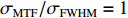
f(x,y) ,则其对应的线扩展函数fL(x)=∫f(x,y)dy ,点扩展函数为fs(x)=f(x,0) 。FWHM尺寸指其点扩展函数fs 的半高全宽,记fs(x) 的最大值为fs.max ,且有fs(x1)=fs(x2)=0.5fs.max ,则束流的FWHM尺寸为|x2−x1| ,该参数主要反映有效应用区域的尺寸,是实验中常用的评价指标。调制传递函数(MTF)等效均匀分布尺寸描述线扩展函数fL(x) 的空间频域特性,设线扩展函数fL(x) 的傅里叶变换为F(k),且有F(k0)=0.5max(F(k)) ,则束流的MTF尺寸为0.705/k0 (0.705为均匀圆盘分布情况下k0 与半高全宽的乘积),该参数对于分布的底宽较为敏感。直线感应加速器中常用的束流分布表征函数有均匀分布(KV)、高斯分布(Gaussian)和本涅特(Bennett)分布,在相同的FWHM时,三种分布的底宽和MTF焦斑依次增大,其分布曲线(线扩展函数)及对应的空间频域曲线如图1所示。在三种分布函数下,FWHM尺寸
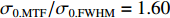
σFWHM 和MTF尺寸σMTF 有线性对应关系,如表1所示。均匀布时σMTF/σFWHM=1 ,高斯分布和本涅特分布的底宽依次增大,σMTF/σFWHM 分别为1.6和2.7,可见σMTF/σFWHM 值与分布底宽呈正相关,后文的分析中将通过σMTF/σFWHM 来判断束流的分布及其底宽特征。 图 1 均匀分布、高斯分布、本涅特分布曲线(a),及对应的空间频域曲线F(k)(b)Figure 1. The curvatures of Kapchiskij-Vladimirskij (KV) distribution, Gaussian distribution, Bennett distribution (a), and their spatial Fourier expansion (b)表 1 不同分布函数下,FWHM尺寸与MTF尺寸的对应关系Table 1. Relationship between the FWHM beam size and the MTF beam size in various distributions
f(x) σFWHM/mm k0/mm−1 σMTF/mm KV 1.00 0.705 1.00 Gaussian 1.00 0.441 1.60 Bennett 1.00 0.258 2.70 2. 能散对束流聚焦影响
2.1 束流聚焦的理论分析
忽略空间电荷效应以及透镜像差,单能电子束在聚焦平面处的均方根尺寸主要受限于束流发射度,近似表示为
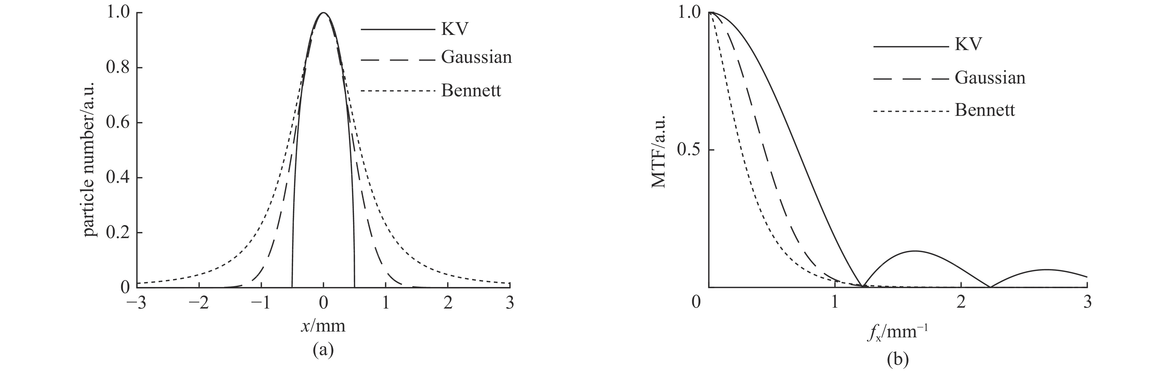
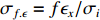
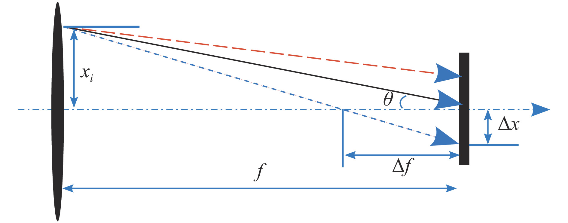
σf.ϵ=fϵx/σi ,其中f、σi、ϵx 分别为焦距,束流初始均方根半径及发射度[12]。焦距与电子束的能量正相关即f∝p0 (p0 为参考电子的能量),一个能量为p 的电子与参考电子的相对能量差异为δ=(p−p0)/p0 ,经过聚焦线圈后焦距差异为Δf=fδ ,如图2所示。一般而言,电磁透镜的焦距远大于焦斑尺寸,则根据图2易得初始位置为xi 、相对能量差异为δ 的电子在焦点处的横向位置为Δx≈Δfθ =fxiδ ,则受能散限制的焦斑尺寸可近似表示为σf.δ=σiσδ ,其中σi 和σδ 分别为束流的均方根半径和均方根能散,即xi 和δ 的均方根值。由于能散与发射度的影响相互独立,最终焦斑尺寸可以表示为 图 2 焦距差异导致的束流横向位置差异示意图Figure 2. The position deviation of electrons induced by focusing length difference
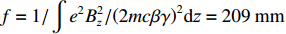
σf=√f2ϵ2x/σ2i+σ2iσ2δ (1) 公式(1)的推导中忽略了束流聚焦前后发射度变化,这在横向非线性力较弱时对于薄束片而言是适用的。以一组实验参数作为计算输入条件:束流的能散分布由加速腔腔压叠加并考虑束流负载效应后获得,中心束片能量17 MeV,如图3虚线所示,流强波形通过B-dot测量获得如图3实线所示,切片发射度
ϵx.slice=200 µm,束流聚焦前尺寸σi=10mm ,根据螺线管磁场求得中心束片的焦距f=1/∫e2B2z/(2mcβγ)2dz=209mm ,其中m,e分别为电子的质量和电荷量,Bz 为聚焦磁场强度,β 为电子经光速归一化的速度,γ 为洛伦兹系数,z为轴向坐标变量。将图3所示束流分为91个1.1 ns的切片(从左到右依次编号,中心束片为#46),将其能量差分别代入公式(1)可估算逐束片聚焦后的均方根尺寸。 图 3 根据实验数据获得的束流的能量和流强分布Figure 3. Current and energy distribution of the electron beam measured in experiment
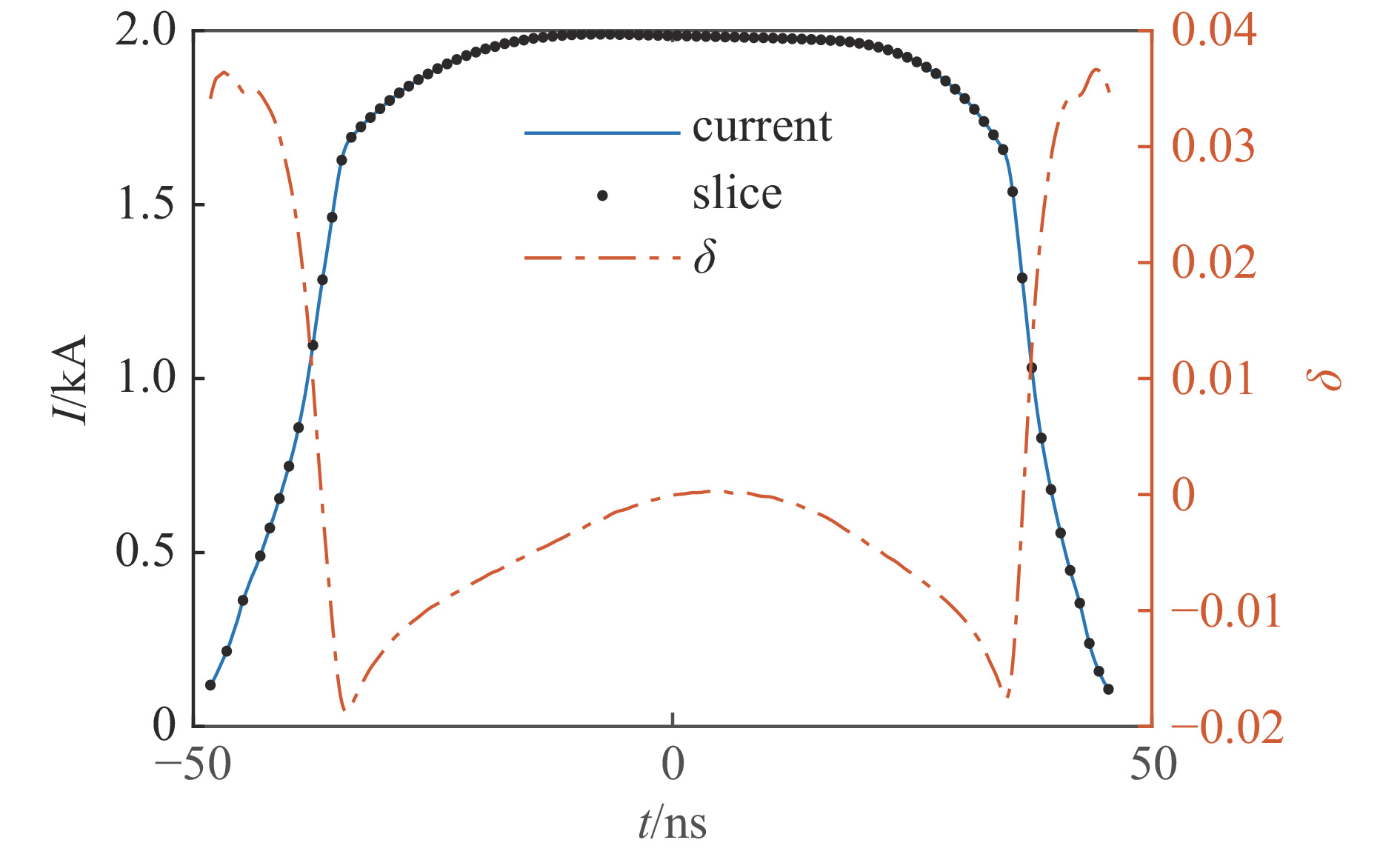
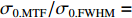
假设聚焦后单束片呈高斯分布,将束片分布按权重叠加即可得到聚焦后整个束流的横向分布,束片权重为其归一化电荷量。根据公式(1)计算得到的中心束片(#46)及整个束流(#1-#91束片叠加)的焦斑分布如图4所示,中心束片以实线表示,整个束流以虚线表示,可见整个束流的底宽明显大于中心束片,但是半高宽差异并不明显。
 图 4 根据公式(1)计算得到的中心束片和整个束流聚焦后的横向分布Figure 4. Transverse profiles of the center slice and of the whole beam calculated with formula (1)
将中心束片聚焦后的MTF和FWHM尺寸分别记为
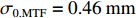
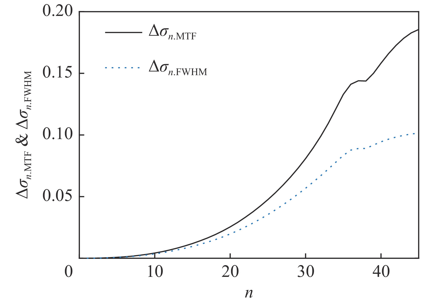
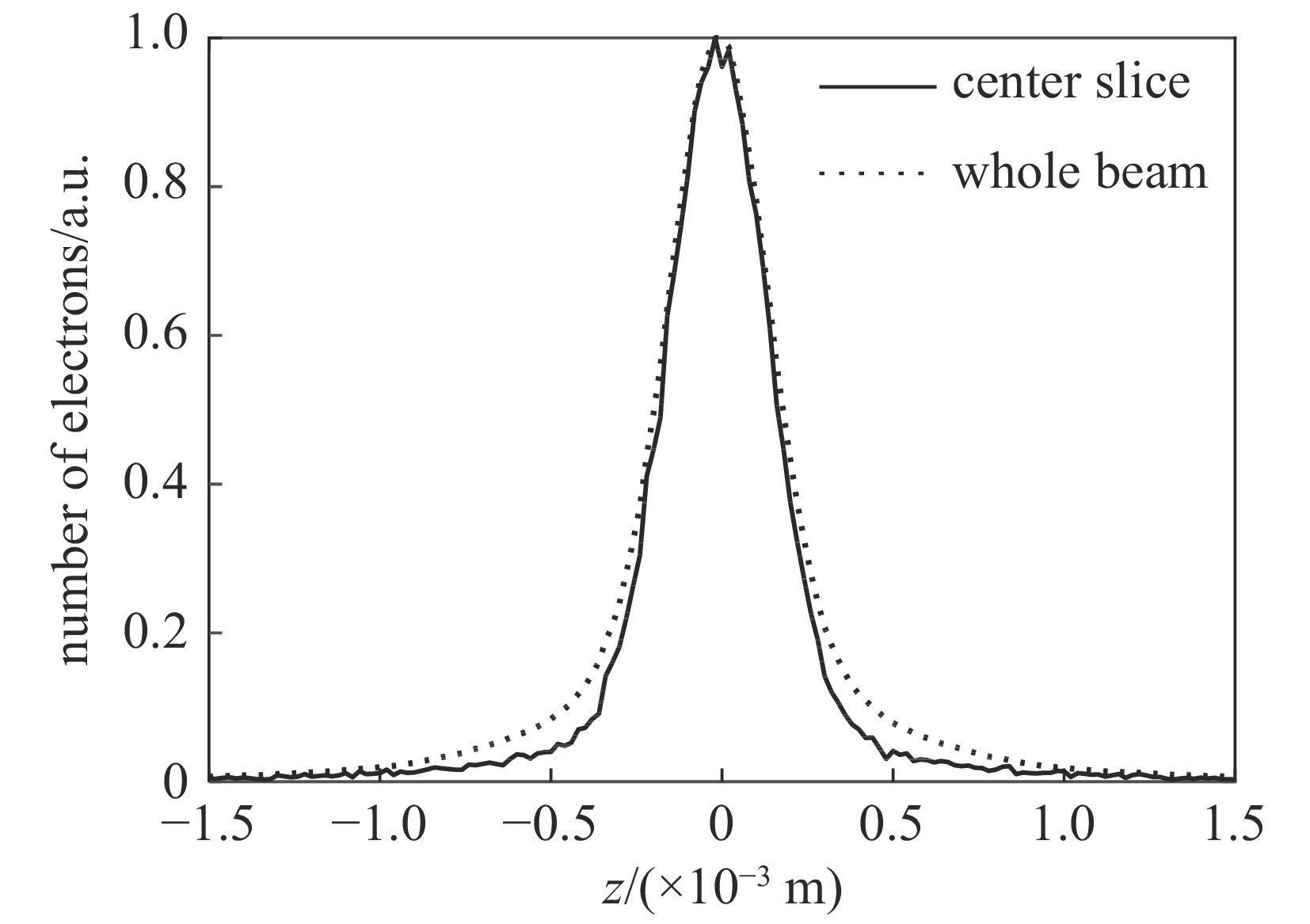
σ0.MTF 和σ0.FWHM ,将#(46-n)号束片至#(46+n)号束片聚焦后叠加分布的MTF和FWHM尺寸分别记为σn.MTF 和σn.FWHM 。根据计算结果可得在焦点位置处σ0.MTF=0.46mm ,σ0.FWHM=0.29mm ,为了分析上升/下降沿叠加后对束流尺寸、分布的影响,进一步计算了n分别取值1~45时叠加分布的MTF/FWHM尺寸相对于中心束片的增长量,将相对增长量表示为Δσn.MTF 和Δσn.FWHM ,其中Δσn.MTF=(σn.MTF−σ0.MTF)/σ0.MTF ,Δσn.FWHM=(σn.FWHM−σ0.FWHM)/σ0.FWHM ,计算结果如图5所示。可见上升/下降沿束片的叠加使得束流绝对尺寸逐渐增大,但MTF尺寸的增长幅度明显高于FWHM尺寸,即Δσn.MTF/Δσn.FWHM 比值随n增大,束流底宽随n的增大逐渐增长。全束流的MTF/FWHM尺寸与中心束片相比分别增长了约18.6%/10.1%,单束片呈高斯分布有σ0.MTF/σ0.FWHM=1.60 ,而全束片叠加后的MTF尺寸与FWHM尺寸比值增长至1.73,对比表1数据可知,全束流分布介于高斯分布和本涅特分布之间。 图 5 根据公式(1)计算得到第#(46−n) 至 #(46+n)号束片叠加后的MTF尺寸(右),其中#46为中心束片Figure 5. MTF size of the electron bunch composed with slice #(46−n) to #(46+n) (right), the results are calculated with formula (1)
上述估算中束片间的唯一差异为能量,可见减小束流能散可以有效的控制束流底宽,减小束流的MTF尺寸。但是由于中间束片的电荷量较大,而上升/下降沿束片电荷量小,束片内的空间电荷力并不一致,因此对束片内分布的影响也不一致,定量评估能散/流强对束流聚焦后尺寸影响需要考虑空间电荷力。
2.2 束流聚焦的模拟研究
为了定量评估能量/流强差异较大的上升/下降沿对束流焦斑尺寸的影响,利用PIC代码ASTRA对逐束片的束流动力学行为进行了模拟仿真(含空间电荷力)。初始束片分布设为高斯分布,每个束片含50000个宏粒子,但在叠加获得聚焦后全束流分布时各束片粒子数按其电荷量加入权重因子。
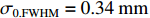
根据模拟结果,焦斑位置处,中心束片的尺寸为
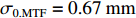
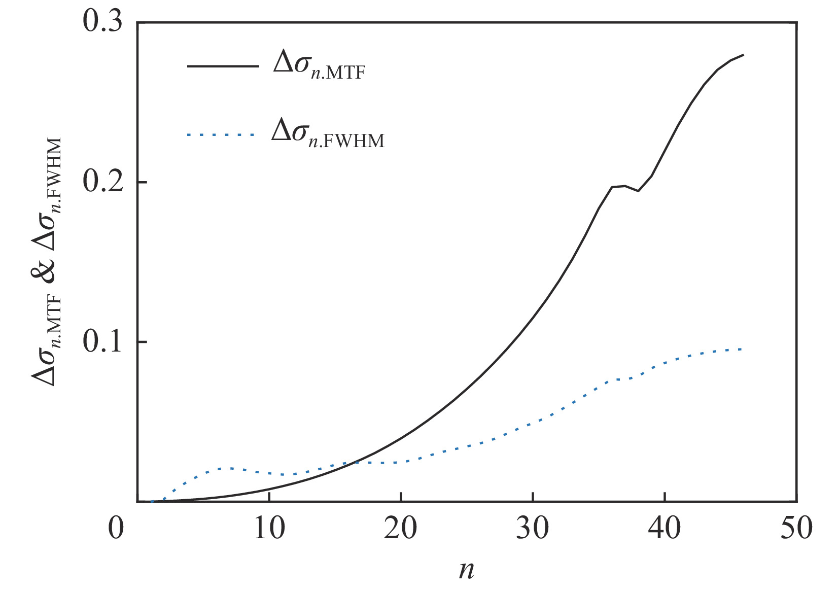
σ0.MTF=0.67mm ,σ0.FWHM=0.34mm ,发射度从200 µm增长至612 µm,尺寸的绝对值与理论分析值存在较大的差异,且σ0.MTF/σ0.FWHM= 1.98,中心束片底宽特征介于高斯分布和本涅特分布之间。可见约2 kA的流强下,空间电荷力会改变单束片聚焦后的分布特征,其非线性力已不可忽略。为了评估上升/下降沿束片叠加导致的束流尺寸增长,与图4、图5的解析结果进行比较,统计了中心束片与全束流聚焦后的分布(如图6所示),以及#(46−n)至#(46+n)号束片叠加分布的尺寸相对于中心束片尺寸的增长(如图7所示)。增长趋势与图5理论计算结果基本一致,全束流的MTF/FWHM尺寸与中心束片相比分别增长了约28.0%、9.8%,全束流的MTF尺寸与FWHM尺寸比值为
2.3 ,更接近于本涅特分布的底宽特征。 图 6 PIC模拟得到的中心束片和整个束流聚焦后的横向分布Figure 6. Transverse profiles of the center slice and of the whole beam simulated with ASTRA
 图 7 PIC模拟得到的第#(46−n) 至 #(46+n)号束片叠加后的MTF尺寸,其中#46为中心束片Figure 7. MTF size of the electron bunch composed with slice #(46−n) to #(46+n) , the results are calculated with the PIC code ASTRA
2.3 计算结果分析
在理论估算(图4)中忽略了空间电荷力,并且假设焦点处束片呈高斯分布,是导致与模拟结果(图5)存在差异的主要原因。对比理论估算结果和模拟结果,虽然聚焦后束流尺寸绝对值差异较大,但是上升/下降沿叠加导致的束流相对尺寸增长趋势却比较一致,即理论模型可用于快速估算上升/下降沿能量差异导致的束流尺寸、底宽相对增长。
理论模型和模拟结果均表明,中心38 ns电子(n=17)的
Δσn.MTF 与Δσn.FWHM 增长量相等,对应的底宽特征与中心束片一致。中心38 ns区域束流强度基本一致,均方根能散为1.7%,则束流平顶区能散小于1.7%时,能散对底宽的影响可以忽略,这需要通过后续的注入器及腔压波形优化来实现。同时注意到从n=37至n=45之间,Δσn.FWHM 变化缓慢只增长约1.7%,而Δσn.MTF 增长8.5%,对束流底宽的增长贡献较大,该区间对应于上升/下降沿各10 ns的电子,流强小,对最终X射线照射量贡献较低,在后续研究中可考虑使用快速踢束器踢除、利用偏转段的能量—位置差异准直、或者利用不同能量束团的感应加速器振荡差异进行准直。3. 结 论
本文根据理论计算和数值模拟结果分析了一台直线感应加速器中上升/下降沿电子能量/流强差异对束流焦斑尺寸、底宽的影响。理论模型忽略了空间电荷力,与模拟结果存在一定差异,但能有效的反应上升/下降沿(能量差异较大)叠加导致的束流尺寸增长趋势,可以作为快速估算的手段。通过对模拟结果的分析,从提升注入器/腔压稳定性和踢除上升/下降沿角度,提出了减小束流底宽的具体指标,为下一步实验设计提供了理论指导。而聚焦前束片大小、位置、会聚角等不一致性对焦斑分布的影响与全束线磁场配置、准直误差等有关,需要从头至尾的PIC模拟来分析,将在后续工作中开展。
-

图 2 抛光区域为凹面,凸面、平面时的剪切应力云图
Figure 2. Shear stress cloud diagram when the polished area is concave, convex and flat
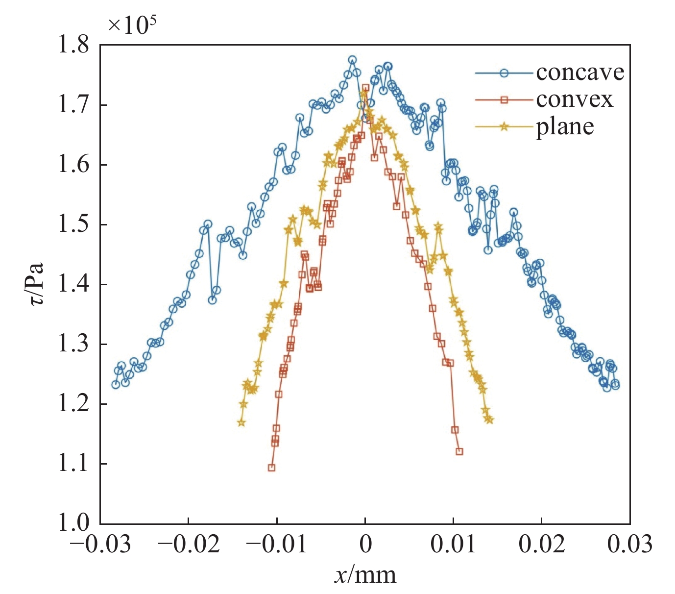
图 3 抛光区域x轴上剪切应力分布曲线图
Figure 3. Shear stress distribution curve on the x-axis of the polished area
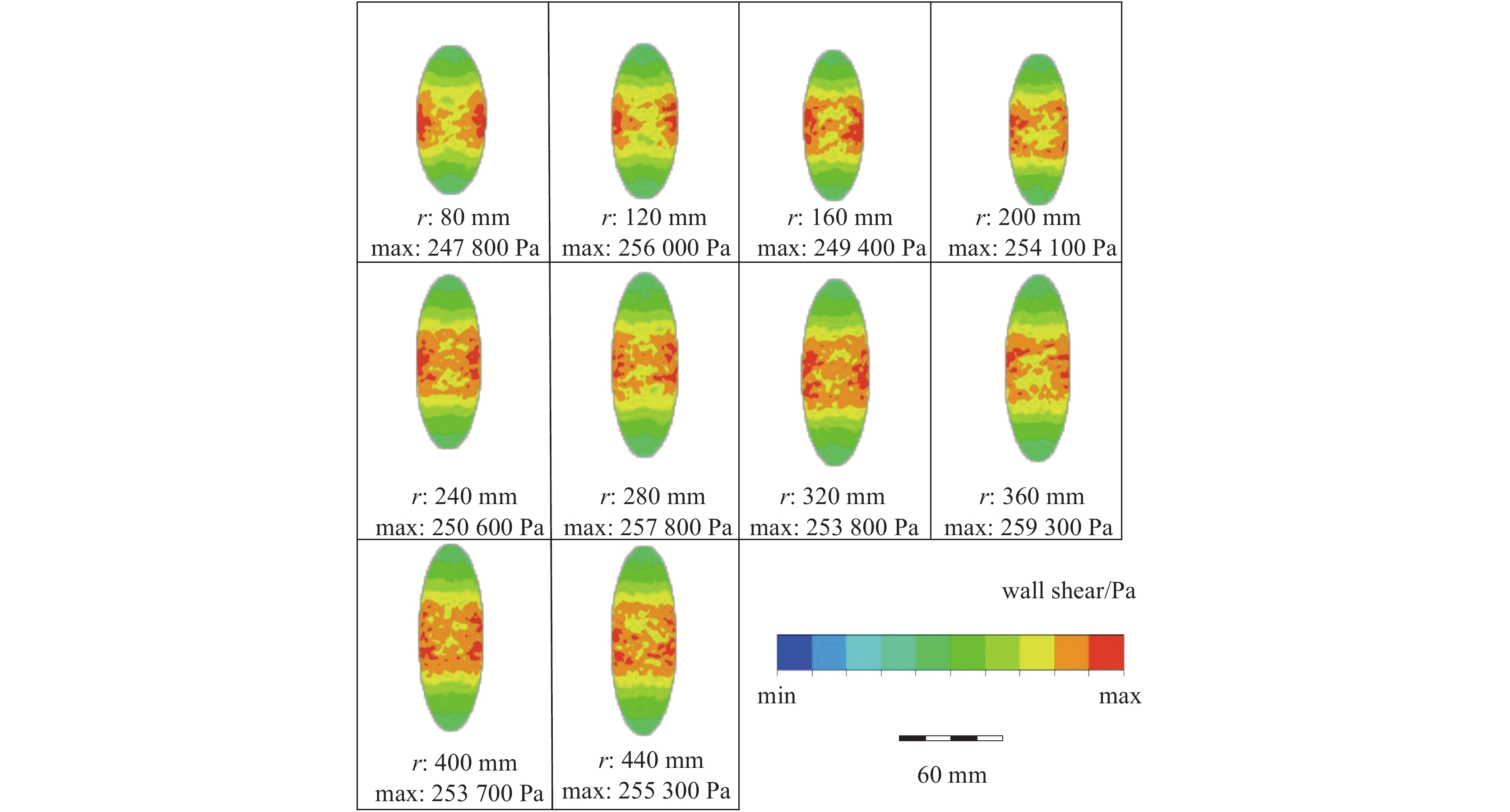
图 4 抛光区域为凸面时曲率大小为80 mm至440 mm的剪切应力云图
Figure 4. Shear stress cloud diagram with curvature of 80 mm to 440 mm when the polished area is convex
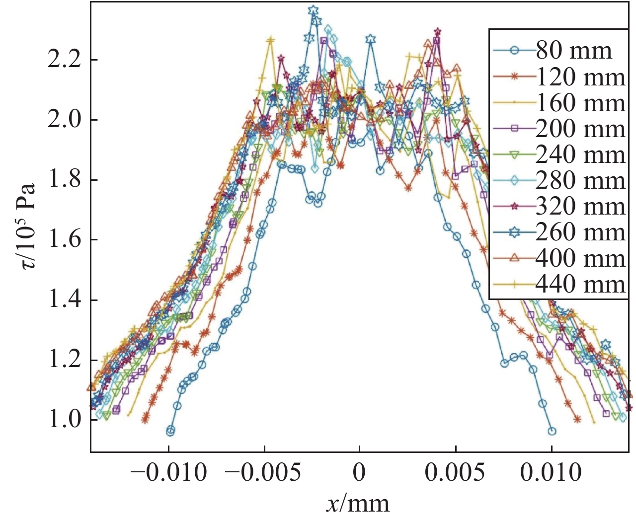
图 5 凸面抛光区域x轴上剪切应力分布曲线图
Figure 5. Shear stress distribution curve on the x-axis of the convex polished area
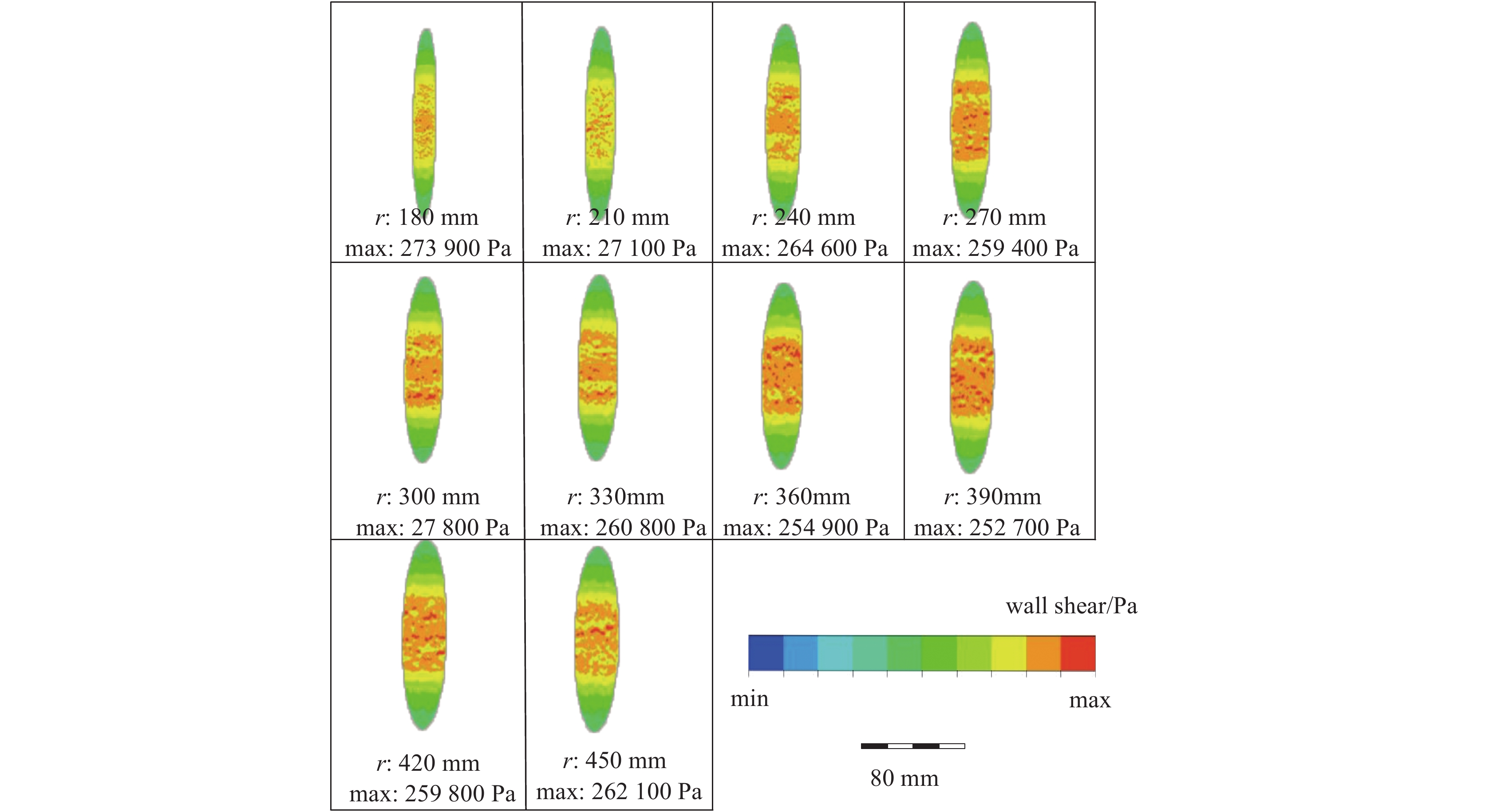
图 6 抛光区域为凹面时曲率大小为180 mm至450 mm的剪切应力云图
Figure 6. Shear stress cloud diagram with a curvature of 180 mm to 450 mm when the polished area is concave
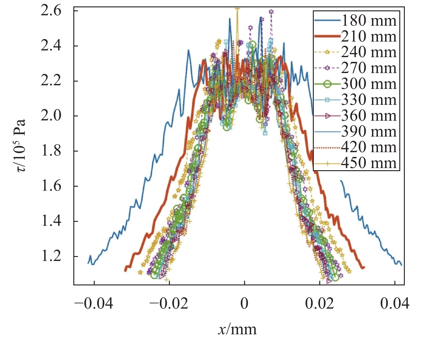
图 7 凹面抛光区域x轴上剪切应力分布曲线图
Figure 7. Shear stress distribution curve on the x-axis of the concave polished area
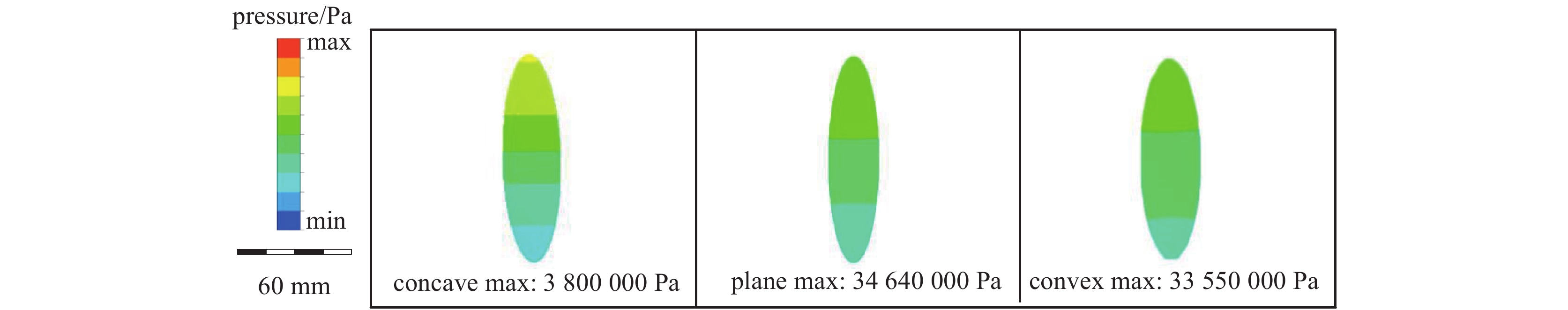
图 8 抛光区域为凹面、凸面、平面的压力云图
Figure 8. Pressure cloud diagram of the concave, convex, and flat polished area
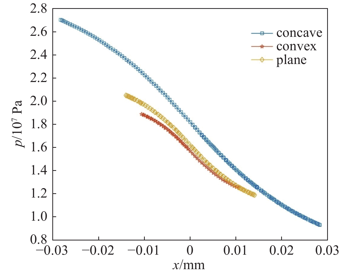
图 9 抛光区域x轴上压力分布曲线图
Figure 9. Pressure distribution curve on the x-axis of the polished area
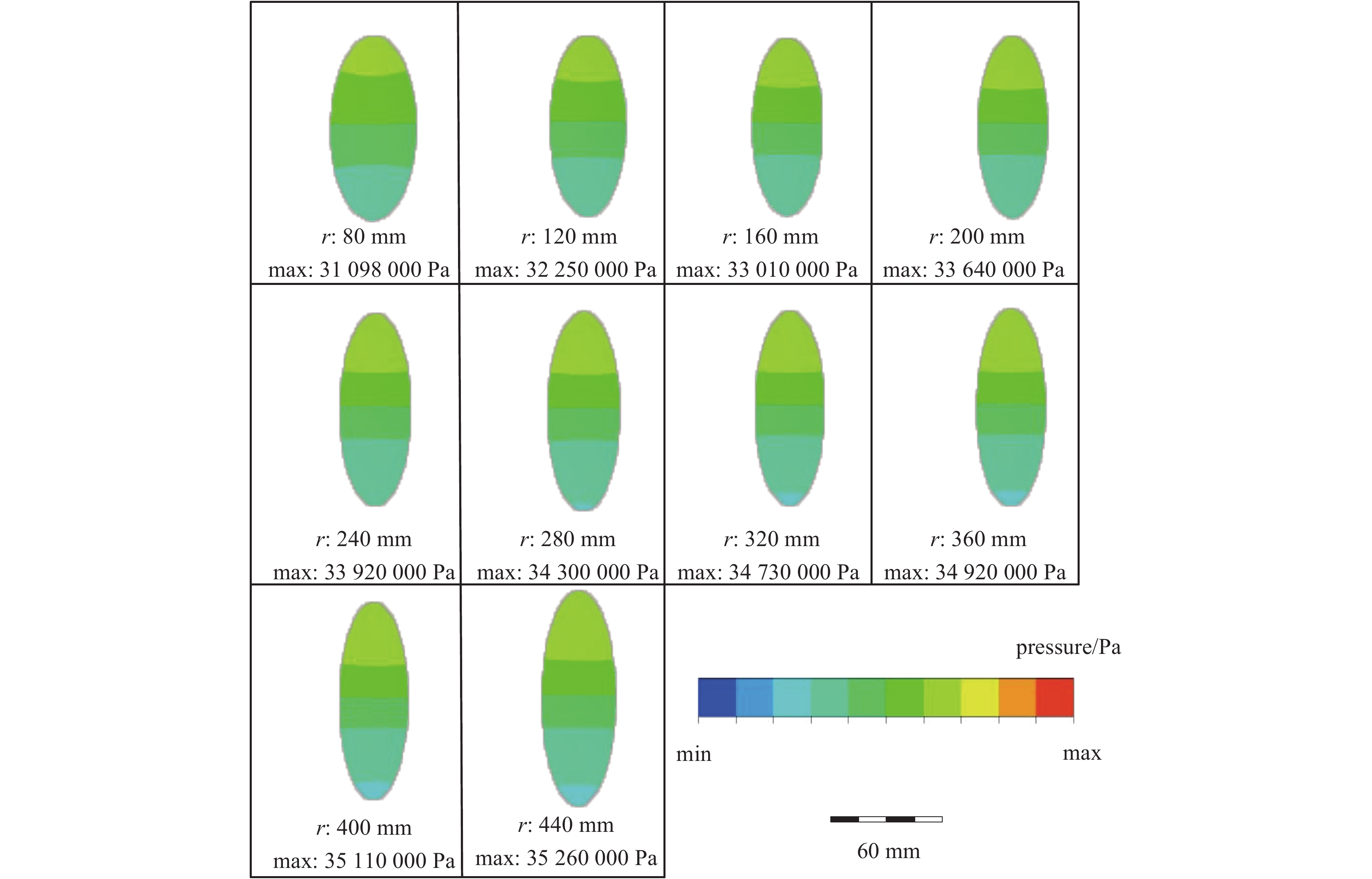
图 10 抛光区域为凸面时曲率大小80 mm至440 mm的压力云图
Figure 10. Pressure cloud diagram with a curvature of 80 mm to 440 mm when the polished area is convex
图 11 凸面抛光区域x轴上压力分布曲线图
Figure 11. Pressure distribution curve on the x-axis of the convex polished area
图 12 抛光区域为凹面时曲率大小180 mm至450 mm压力云图
Figure 12. Pressure cloud diagram with curvature of 180 mm to 450 mm when the polished area is concave

图 13 凹面抛光区域x轴上压力分布曲线图
Figure 13. Pressure distribution curve on the x-axis of the concave polished area
表 1 选用的磁流变抛光工艺参数
Table 1. Selected magnetorheological polishing process parameters
consistency index,
k/(sn−2/m)power law
indexyield stress
threshold ptemporary shear
rate/(1/s)flow coefficient
nribbon
thickness/mmribbon
width/mmpolishing wheel
speed v/(m/s)inlet and outlet
pressure/Pa59.01 0.7301 13861.84 100 0.3755 1.5 15 4.71 101000  下载: 导出CSV
表 2 不同形状抛光区域
Table 2. Polished areas of different shapes
No. immersion depth h/mm shape 1 1.0 concave 2 1.0 convex 3 1.0 plane
下载: 导出CSV
表 3 选取的抛光区域曲率大小参数
Table 3. Curvature parameters of the selected polishing area
No. immersion
depth h/mmconvex
curvature r/mmconcave
curvature r/mm1 1.0 80 180 2 1.0 120 210 3 1.0 160 240 4 1.0 200 270 5 1.0 240 300 6 1.0 280 330 7 1.0 320 360 8 1.0 360 390 9 1.0 400 420 10 1.0 440 450
下载: 导出CSV
表 4 不同形状抛光区域
Table 4. Polished areas of different shapes
No. immersion depth h/mm shape 1 1.0 concave 2 1.0 convex 3 1.0 plane
下载: 导出CSV
表 5 选取的抛光区域曲率大小参数
Table 5. Curvature parameters of the selected polishing area
No. immersion
depth h/mmconvex
curvature r/mmconcave
curvature r/mm1 1.0 80 180 2 1.0 120 210 3 1.0 160 240 4 1.0 200 270 5 1.0 240 300 6 1.0 280 330 7 1.0 320 360 8 1.0 360 390 9 1.0 400 420 10 1.0 440 450
下载: 导出CSV
-
[1] Awwal A, Bowers M, Wisoff J, et al. Status of NIF laser and high power laser research at LLNL[C]//SPIE Lase. 2017: 1008403. [2] 高伟, 魏齐龙, 李晓媛, 等. 磁流变抛光与磁流变液: 原理与研究现状[J]. 磁性材料及器件, 2015, 46(2):68-73. (Gao Wei, Wei Qilong, Li Xiaoyuan, et al. Magnetorheological polishing and magnetorheological fluids: principles and research status[J]. Magnetic Materials and Devices, 2015, 46(2): 68-73 doi: 10.3969/j.issn.1001-3830.2015.02.016 [3] Yin Yuehong, Zhang Yifan, Dai Yifan, et al. Novel magneto-rheological finishing process of KDP crystal by controlling fluid-crystal temperature difference to restrain deliquescence[J]. CIRP Annals, 2018, 67(1): 587-590. doi: 10.1016/j.cirp.2018.04.058 [4] Jain V K, Ranjan P, Suri V K, et al. Chemo-mechanical magneto-rheological finishing (CMMRF) of silicon for microelectronics applications[J]. CIRP Annals, 2010, 59(1): 323-328. doi: 10.1016/j.cirp.2010.03.106 [5] Khan D A, Alam Z, Jha S. Nanofinishing of copper using ball end magnetorheological finishing (BEMRF) process[C]//ASME International Mechanical Engineering Congress and Exposition. 2016. [6] 张峰, 余景池, 张学军, 等. 磁流变抛光技术[J]. 光学精密工程, 1999, 7(5):1-8. (Zhang Feng, Yu Jingchi, Zhang Xuejun, et al. Magnetorheological polishing technology[J]. Optics and Precision Engineering, 1999, 7(5): 1-8 doi: 10.3321/j.issn:1004-924X.1999.05.001 [7] 杨建国, 李中会, 李蓓智, 等. 精密磁流变抛光装置的设计与应用[J]. 机械设计与制造, 2010, 2010(9):60-62. (Yang Jianguo, Li Zhonghui, Li Beizhi, et al. Design and application of precision magnetorheological polishing device[J]. Machine Design and Manufacturing, 2010, 2010(9): 60-62 doi: 10.3969/j.issn.1001-3997.2010.09.026 [8] 成连民, 李蓓智, 杨建国, 等. 磁流变抛光工艺参数的研究[J]. 机械, 2009, 36(6):11-16. (Cheng Lianmin, Li Beizhi, Yang Jianguo, et al. Research on the process parameters of magnetorheological polishing[J]. Machinery, 2009, 36(6): 11-16 [9] 甄宗坤, 蔡东健. 基于面状几何基元的特征自动提取技术[J]. 水利与建筑工程学报, 2018, 16(2):147-151. (Zhen Zongkun, Cai Dongjian. Automatic feature extraction technology based on planar geometric primitives[J]. Journal of Water Resources and Architectural Engineering, 2018, 16(2): 147-151 doi: 10.3969/j.issn.1672-1144.2018.02.028 [10] 张云, 冯之敬, 赵广木. 磁流变抛光工具及其去除函数[J]. 清华大学学报(自然科学版), 2004, 2004(2):190-193. (Zhang Yun, Feng Zhijing, Zhao Guangmu. Magnetorheological polishing tool and its removal function[J]. Journal of Tsinghua University (Natural Science Edition), 2004, 2004(2): 190-193 doi: 10.3321/j.issn:1000-0054.2004.02.015 [11] 石峰, 戴一帆, 彭小强, 等. 磁流变抛光过程的材料去除三维模型[J]. 中国机械工程, 2009, 20(6):644-648. (Shi Feng, Dai Yifan, Peng Xiaoqiang, et al. Three-dimensional model of material removal in magnetorheological polishing process[J]. China Mechanical Engineering, 2009, 20(6): 644-648 doi: 10.3321/j.issn:1004-132X.2009.06.004 [12] Liu Jiabao, Li Xiaoyuan, Zhang Yunfei, et al. Predicting the material removal rate (MRR) in surface magnetorheological finishing (MRF) based on the synergistic effect of pressure and shear stress[J]. Applied Surface Science, 2020, 504: 144492. doi: 10.1016/j.apsusc.2019.144492 [13] Chen Mingjun, Liu Henan, Cheng Jian, et al. Model of the material removal function and an experimental study on a magnetorheological finishing process using a small ball-end permanent-magnet polishing head[J]. Applied Optics, 2017, 56(19): 5573-5582. doi: 10.1364/AO.56.005573 [14] 李耀明, 沈兴全, 王爱玲. 磁流变抛光技术的工艺试验[J]. 金刚石与磨料磨具工程, 2009, 2009(5):64-66. (Li Yaoming, Shen Xingquan, Wang Ailing. Process test of magnetorheological polishing technology[J]. Diamond and Abrasive Engineering, 2009, 2009(5): 64-66 doi: 10.3969/j.issn.1006-852X.2009.05.013 [15] 秦北志, 杨李茗, 朱日宏, 等. 光学元件精密加工中的磁流变抛光技术工艺参数[J]. 强激光与粒子束, 2013, 25(9):2281-2286. (Qin Beizhi, Yang Liming, Zhu Rihong, et al. Process parameters of magnetorheological polishing technology in precision machining of optical components[J]. High Power Laser and Particle Beam, 2013, 25(9): 2281-2286 doi: 10.3788/HPLPB20132509.2281 [16] 李发胜, 张平. 抛光用磁流变液的研究[J]. 功能材料, 2006(8):1187-1190. (Li Fasheng, Zhang Ping. Research on magnetorheological fluid for polishing[J]. Functional Materials, 2006(8): 1187-1190 doi: 10.3321/j.issn:1001-9731.2006.08.001 [17] 沙树静, 胡锦飞, 张和权. 磁流变抛光技术发展[J]. 机械工程师, 2018, 2018(7):5-8. (Sha Shujing, Hu Jinfei, Zhang Hequan. Development of magnetorheological polishing technology[J]. Mechanical Engineer, 2018, 2018(7): 5-8 doi: 10.3969/j.issn.1002-2333.2018.07.002 期刊类型引用(1)
1. 顾余辉. 直线加速器维修维护及质控措施研究分析. 中国设备工程. 2024(07): 48-50 .  百度学术
百度学术其他类型引用(0)
-


 下载:
下载:


 点击查看大图
计量
- 文章访问数: 833
- HTML全文浏览量: 335
- PDF下载量: 23
- 被引次数: 1
