

Investigation on wide-angle scanning technology for high power resonant waveguide slot array antenna
-
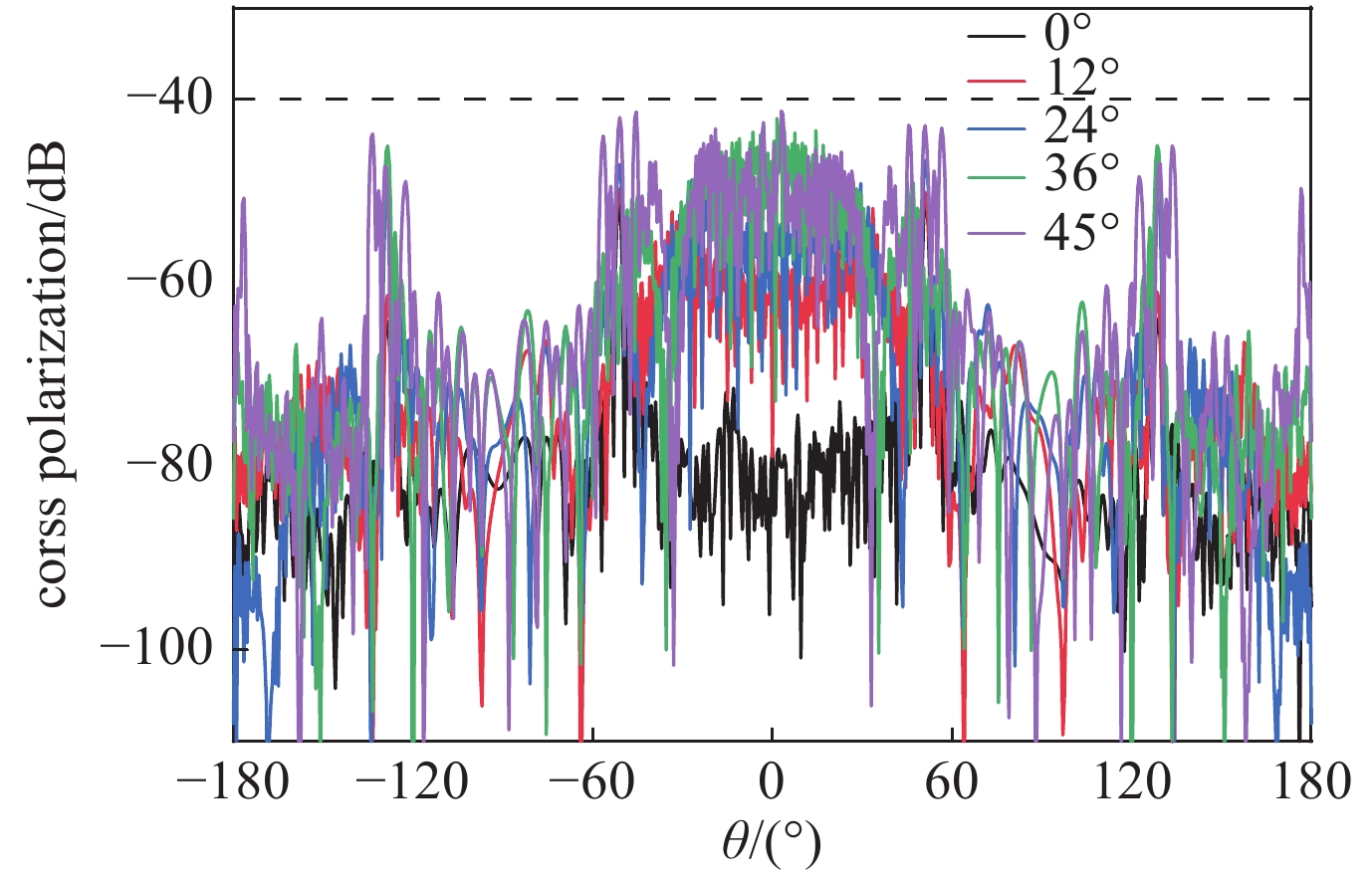
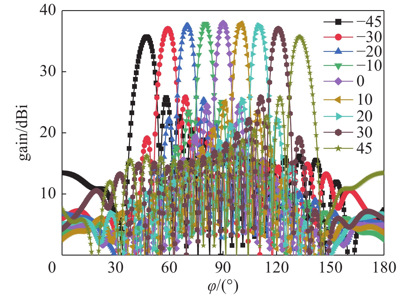
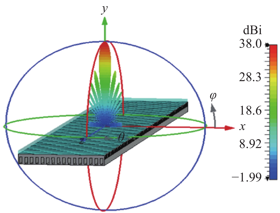
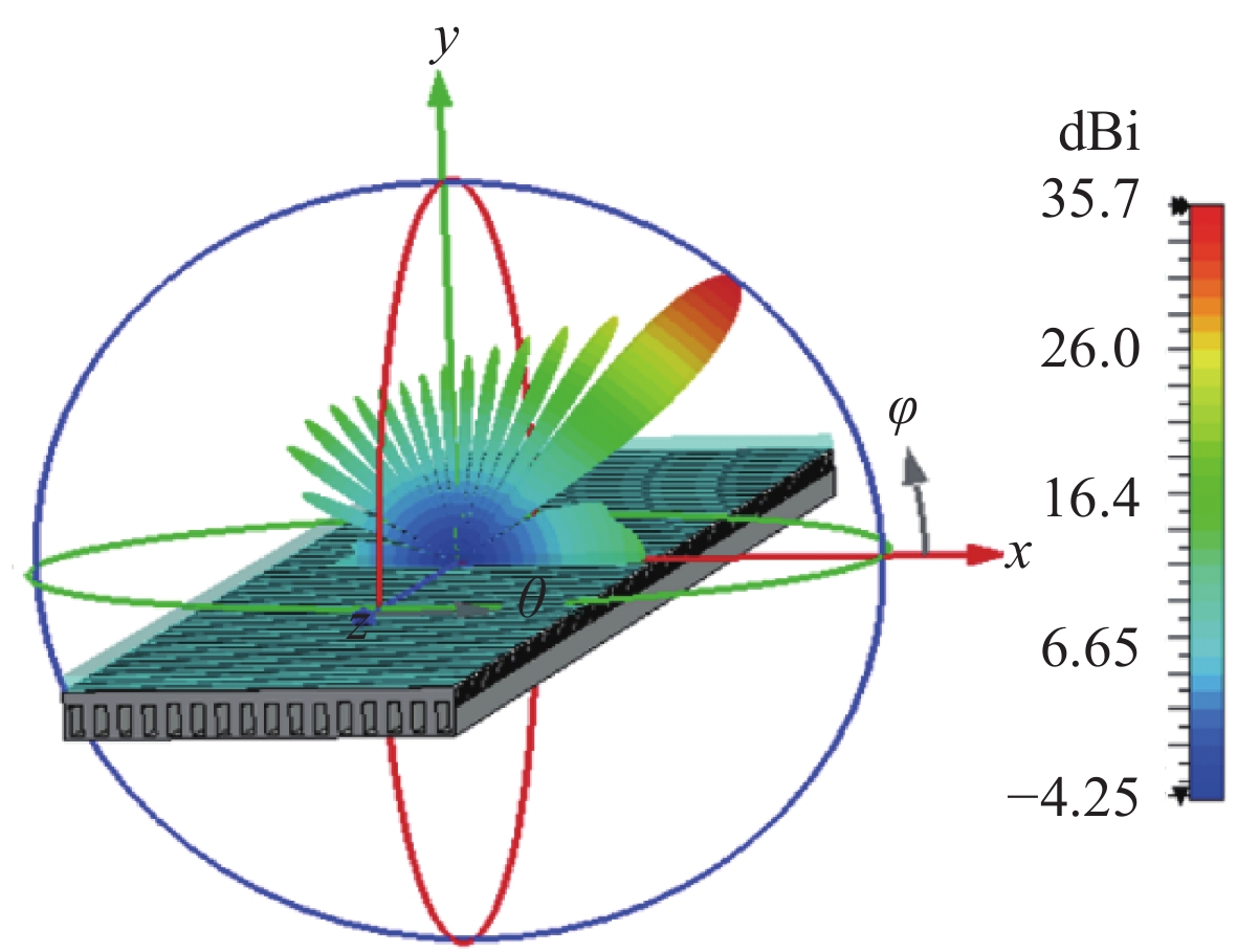
摘要: 在传统高功率缝隙波导阵列中,缝隙间的相互耦合严重影响了阵列的宽角扫描能力。以实现阵列宽角波束扫描为目标,通过分析阵列扫描特性,从提高缝隙阵元间隔离度的角度出发,提出在阵列中引入隔离栅结构,降低了阵元间耦合对阵列大角度扫描时的影响。在此基础上,设计了基于波导窄边斜缝的谐振式阵列天线,采用电磁仿真软件优化阵列。数值模拟结果表明,未采取措施前阵列的最大扫描范围为±34°,引入隔离栅后扫描范围可扩大至±45°,波导端口S11≤−10 dB,增益仅下降了2.3 dB,单根缝隙波导功率容量达330 MW,有应用于高功率微波领域的潜质。Abstract: In traditional high-power slotted waveguide arrays, the mutual coupling between the adjacent slots seriously affects the wide-angle scanning ability of the array. To improve beam scanning ability, the scanning characteristics of the array has been analyzed. An isolation barrier has been introduced into the traditional slotted waveguide array to suppress the cross polarization caused by the inclined slots and improve the isolation of the elements. In this paper, an antenna array based on the rectangular waveguide with resonant slot in the narrow-wall has been proposed and designed, the simulation results show that the traditional structure can only scan to ±34° when S11≤−10 dB. But after loading the isolation barrier, the scanning range is expanded to ±45° with 2.3 dB gain reduction. Moreover, the power handling capacity of a single slotted waveguide is more than 330 MW, which indicates application potentials of this antenna in high power microwave (HPM) field.
-
[1] Benford J, Swegle J A, Schamiloglu E. High power microwaves[M]. 2nd ed. New York: Taylor & Francis, 2007. [2] Benford J. Space applications of high-power microwaves[J]. IEEE Transactions on Plasma Science, 2008, 36(3): 569-581. doi: 10.1109/TPS.2008.923760 [3] Gaponov A V, Flyagin V A, Fix A S, et al. Some perspectives on the use of powerful gyrotrons for the electron-cyclotron plasma heating in large tokamaks[J]. International Journal of Infrared and Millimeter Waves, 1980, 1(3): 351-372. doi: 10.1007/BF01007321 [4] Clunie D. The design, construction and testing of an experimental high power, short-pulse radar, strong microwave in plasmas[M]. Nizhny Novgorod: Novgorod University Press, 1997. [5] 秦洪才, 袁成卫, 宁辉, 等. 高功率平板波导螺旋阵列天线设计[J]. 强激光与粒子束, 2021, 33:023002 doi: 10.11884/HPLPB202133.200252Qin Hongcai, Yuan Chengwei, Ning Hui, et al. Design of high power helical array antenna fed from planar waveguide[J]. High Power Laser and Particle Beams, 2021, 33: 023002 doi: 10.11884/HPLPB202133.200252 [6] 杨一明, 袁成卫, 钱宝良. 波导缝隙阵列天线高功率微波应用探索[J]. 强激光与粒子束, 2013, 25(10):2648-2652 doi: 10.3788/HPLPB20132510.2648Yang Yiming, Yuan Chengwei, Qian Baoliang. Beam steering antenna for high power microwave application[J]. High Power Laser and Particle Beams, 2013, 25(10): 2648-2652 doi: 10.3788/HPLPB20132510.2648 [7] 廖勇, 孟凡宝, 张现福, 等. L波段高功率波导缝隙阵设计与数值模拟[J]. 强激光与粒子束, 2016, 28:113003 doi: 10.11884/HPLPB201628.160069Liao Yong, Meng Fanbao, Zhang Xianfu, et al. Design and simulation of L-band high power microwave antenna based on rectangular waveguides with longitudinal shunt slots[J]. High Power Laser and Particle Beams, 2016, 28: 113003 doi: 10.11884/HPLPB201628.160069 [8] 刘斌, 谷胜明, 孟明霞, 等. 一种Ka频段高效率圆极化宽角扫描波导缝隙相控阵天线[J]. 电子与信息学报, 2021, 43(6):1630-1636 doi: 10.11999/JEIT200392Liu Bin, Gu Shengming, Meng Mingxia, et al. A circularly polarized wide-scan waveguide slot phased array antenna with high efficiency for Ka band application[J]. Journal of Electronics & Information Technology, 2021, 43(6): 1630-1636 doi: 10.11999/JEIT200392 [9] 杨彦炯. K波段低副瓣波导缝隙驻波阵设计[J]. 现代导航, 2018, 9(4):287-290 doi: 10.3969/j.issn.1674-7976.2018.04.012Yang Yanjiong. Design of K-band standing wave array waveguide slot antenna with low sidelobe[J]. Modern Navigation, 2018, 9(4): 287-290 doi: 10.3969/j.issn.1674-7976.2018.04.012 [10] 林昌禄. 近代天线设计[M]. 北京: 人民邮电出版社, 1993Lin Changlu. Modern antenna design[M]. Beijing: Posts & Telecom Press, 1993 [11] 钟顺时, 费桐秋, 孙玉林. 波导窄边缝隙阵天线的设计[J]. 西北电讯工程学院学报, 1976(1):165-184Zhong Shunshi, Fei Tongqiu, Sun Yulin. Design of narrow-side slot array antenna of waveguide[J]. Journal of Xidian University, 1976(1): 165-184 [12] Collin R E. Antenna and radio wave propagation[M]. New York: McGraw-Hill, 1985. [13] Liao Yong, Meng Fanbao, Xu Gang, et al. Analysis of wide-angle scanning of HPM waveguide slot array antenna[J]. High Power Laser and Particle Beams, 2018, 30: 033002. [14] Katoch M, Abegaonkar M, Basu A, et al. Compact microstrip phase shifter for beam steering antenna[C]//IEEE Asia-Pacific Microwave Conference. 2016: 1-5. [15] 黄惠军, 常超, 侯青, 等. 真空条件下介质窗表面微波击穿实验[J]. 强激光与粒子束, 2010, 22(4):845-848 doi: 10.3788/HPLPB20102204.0845Huang Huijun, Chang Chao, Hou Qing, et al. Experimental studies on dielectric surface breakdown at vacuum conditions under high-power microwave excitation[J]. High Power Laser and Particle Beams, 2010, 22(4): 845-848 doi: 10.3788/HPLPB20102204.0845 -

 下载:
下载:


 点击查看大图

图(15)
计量
- 文章访问数: 1702
- HTML全文浏览量: 698
- PDF下载量: 197
- 被引次数: 0
