

Dual-branch loaded L-band broadband high isolation directional coupler
-
摘要: 提出了一种小型化双枝节加载的L波段微带线定向耦合器。使用功率相消技术提高定向耦合器的隔离度,并且采用两根长度不同的加载枝节分别在两个相近的频点上反射信号,从而实现耦合器的带宽扩展;同时采用缺陷地结构的慢波特性减小该定向耦合器的物理尺寸,并利用缺陷地结构产生的陷波,合并上述两根枝节反射抵消产生的的两个陷波,进一步提高定向耦合器的带宽和隔离度。该耦合器工作在L波段,耦合度约为10 dB,在整个L波段内的隔离度均优于−20 dB,最大约为−52.81 dB,相对带宽为60%。最后对设计的定向耦合器进行加工和测试,测试与仿真结果一致性较好,证明了该电路的可行性。Abstract: This paper presents a miniaturized L-band microstrip line directional coupler loaded with double branches. Power cancellation technology is used to increase the isolation of the directional coupler, and two loading branches with different lengths are used to reflect signals at two similar frequency points respectively, so as to realize the bandwidth expansion of the coupler; at the same time, the slow wave characteristics of the defective ground structure are used to reduce the physical size of the directional coupler, and the notch generated by the defective ground structure is used to combine the two notch waves generated by the reflection of the two branches to further improve the bandwidth and isolation of the directional coupler. The coupler works in the L-band, the coupling is about 10 dB, the isolation in the entire L-band is better than −20 dB, and the maximum is about −52.81 dB, and the fractional bandwidth is 60%. Finally, the designed directional coupler is processed and tested, and the test and simulation results are in good agreement, which proves the feasibility of the circuit.
-

图 1 本文设计的定向耦合器结构图
Figure 1. Structure of the directional coupler designed in this paper
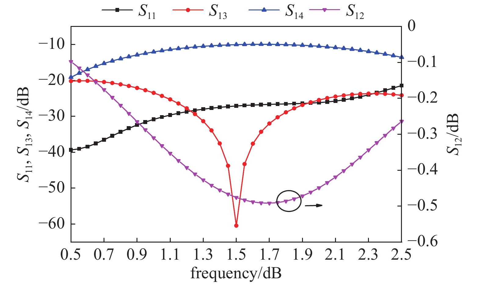
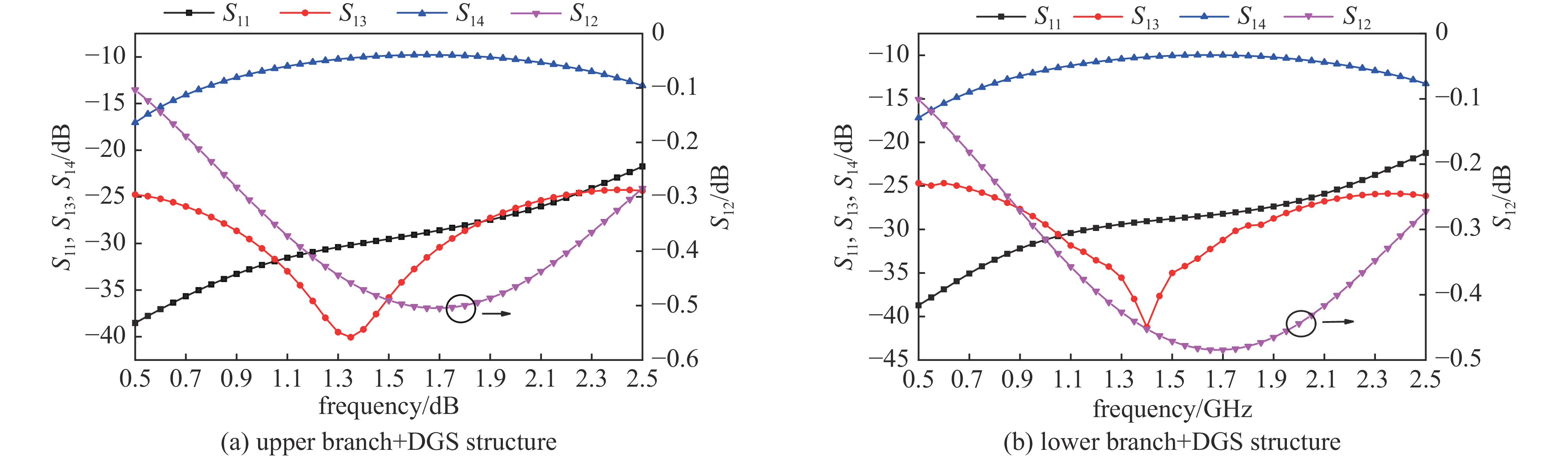
图 2 本文定向耦合器的仿真结果
Figure 2. Simulation results of the directional coupler in this paper
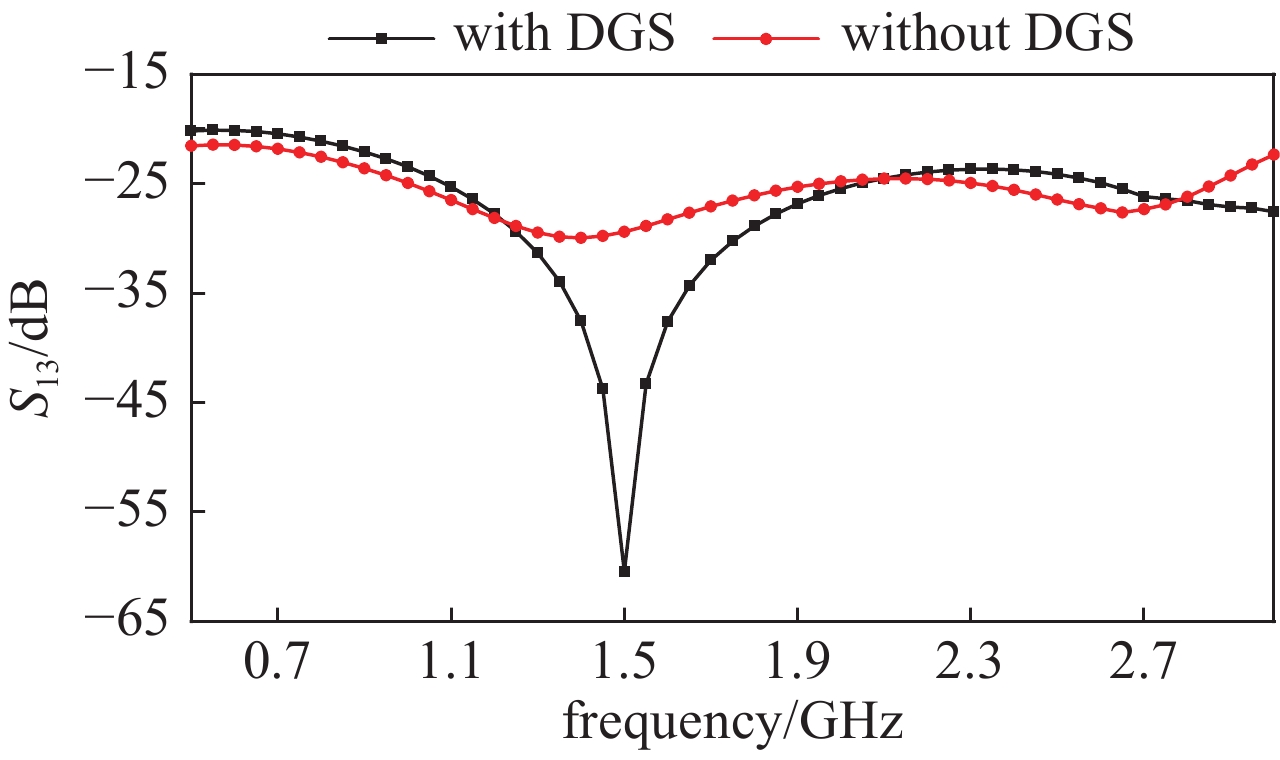
图 4 有无DGS结构隔离度仿真结果图
Figure 4. Simulation results with or without DGS structure isolation

图 6 所设计定向耦合器表面电流分布
Figure 6. Surface current distribution of the designed directional coupler
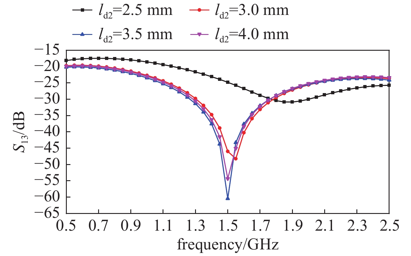
图 7 两根枝节间距离对隔离度的影响
Figure 7. Influence of the distance between two branches on the isolation

图 8 本文提出的定向耦合器实物图
Figure 8. The physical diagram of the directional coupler proposed in this paper
-
[1] Tang C W, Chen M G, Lin Y S. Broadband microstrip branch-line coupler with defected ground structure[J]. Electron Lett, 2006, 42(25): 1458-1460. doi: 10.1049/el:20063025 [2] Yoon H J, Min B W. Two section wideband 90° hybrid coupler using parallel-coupled three-line[J]. IEEE Trans Microw Theory Tech, 2017, 27(6): 548-550. [3] Cao Y Y, Wu Y W, Jiang Z, et al. A compact millimeter-wave planar directional coupled crossover with a wide bandwidth[J]. IEEE Microwave and Wireless Components Letters, 2020: 1-4. [4] Muraguchi M, Yukitake T, Naito Y. Design of compact directional couplers for UWB applications[J]. IEEE Trans Microw Theory Tech, 2007, 55(2): 189-194. doi: 10.1109/TMTT.2006.889150 [5] Wan K K, Moon Q L, Jin H K. A passive circulator with high isolation using a directional coupler for RFID[J]. IEEE MTT-S International Microwave Symposium Digest, 2006: 1177-1178. [6] 陈蕾, 尚宇, 魏峰. 一种新的缺陷地微带线定向耦合器[J]. 西安工业大学学报, 2008, 28(4):372-374. (Chen Lei, Shang Yu, Wei Feng. A new defective ground microstrip line directional coupler[J]. Journal of Xi'an Technological University, 2008, 28(4): 372-374 doi: 10.3969/j.issn.1673-9965.2008.04.012 [7] Chang W S, Liang C H, Chang C Y. Wideband high-isolation and perfect-balance microstrip rat-race coupler[J]. IEEE Electronics Letters, 2012, 48(7): 382-383. doi: 10.1049/el.2012.0227 [8] Muller J, Pham M N, Jacob A F. Directional coupler compensation with optimally positioned capacitances[J]. IEEE Transactions on Microwave Theory and Techniques, 2011, 59(11): 2824-2832. doi: 10.1109/TMTT.2011.2165961 [9] Zhang Z H, Rautschke F, Nguyen H. A novel structure of high directivity broadband microstrip coupler[C]//IEEE MTT-S International Microwave and Optoelectronics Conference. 2015: 1-4. [10] 周越, 申冀湘, 宋亮. 电感补偿高方向性的微带定向耦合器[J]. 无线电工程, 2013, 43(7):38-40. (Zhou Yue, Shen Jixiang, Song Liang. Microstrip directional coupler with inductance compensation and high directivity[J]. Radio Engineering, 2013, 43(7): 38-40 doi: 10.3969/j.issn.1003-3106.2013.07.013 [11] Ha J, Shin W, Lee Y. An inductive-loading method for directivity enhancement of microstrip coupled-line couplers[J]. IEEE Microwave and Wireless Components Letters, 2017, 27(4): 356-358. doi: 10.1109/LMWC.2017.2678422 [12] 杨宇斌. 带短路支节的高隔离度分支线定向耦合器设计研究[D]. 南京: 南京邮电大学, 2015Yang Yubin. Design and research of high isolation branch line directional coupler with short-circuit branch[D]. Nanjing: Nanjing University of Posts and Telecommunications, 2015 [13] Rahman A, Verma A K, Boutejdar A, et al. Control of bandstop response of microstrip low-pass filter using slot in ground plane[J]. IEEE Transactions on Microwave Theory and Techniques, 2004, 52(3): 1008. doi: 10.1109/TMTT.2004.823587 [14] Lim J S, Kim C S, Lee Y T, et al. Design of low-pass filters using defected ground structure and compensated microstrip line[J]. Electron Lett, 2002, 38(22): 1357. doi: 10.1049/el:20020889 [15] Lim J S, Kim C S, Ahn D, et al. Design of the low-pass filters using defected ground structure[J]. IEEE MTT, 2005, 53(8): 2539. doi: 10.1109/TMTT.2005.852765 [16] Guo Huili, Xin Huajiang, Xiao Mingzhong. A novel defected ground structure and its application to a low-pass filter[J]. Microwave Opt Technol Lett, 2006, 48(9): 1760. doi: 10.1002/mop.21750 -

 下载:
下载:

 点击查看大图
计量
- 文章访问数: 2291
- HTML全文浏览量: 985
- PDF下载量: 210
- 被引次数: 0
