Quality quantification in pulsed power supply for synchrotron magnet
-
摘要: 同步加速器中,磁铁励磁电流高频的纹波误差能够引起磁场纹波,进而导致束流接受度降低。励磁电流低频的跟踪误差会影响磁场与束流能量的匹配程度,同时会引起束流闭合轨道畸变。为了从以上两方面评估励磁电流误差对于束流的影响,研究了HIAF BRing二极磁铁磁场纹波与励磁电流纹波之间的关系,并提出了一套基于高低频分离的脉冲励磁电流质量量化方法。该方法利用高斯平滑处理得到励磁电流低频的跟踪误差分量和高频的纹波误差分量,采用三倍标准差作为励磁电流跟踪性能及纹波质量的量化指标。方法中低通滤波器参数由磁铁磁场纹波与励磁电流纹波的响应关系确定,该方法同时准确地量化评估了磁场纹波质量。此外,由该方法得到的电流跟踪误差波形能够应用于同步加速器励磁电源的给定修正,进而提高磁场与束流能量匹配程度。Abstract: In synchrotrons, the high-frequency ripple error of magnet excitation current causes magnetic field ripple, which leads to decreased beam acceptance. The low-frequency tracking error of the excitation current would affect the matching degree of magnetic field and beam energy, which would cause the closed orbit distortion of the beam. The correlation between magnetic field ripple and excitation current ripple of HIAF BRing dipole magnet is studied in this paper. The current quality quantification methods based on high and low-frequency separation are proposed, which evaluate the effect of excitation current error on the beam. The low-frequency tracking error and high-frequency ripple error of the excitation current are obtained by Gaussian smoothing. Three times the standard deviation is used as the quantification indicator of the excitation current in terms of ripple and tracking error. Since parameters of the low-pass filter are determined by the response relationship between magnetic field ripple and excitation current ripple, this method could accurately quantify the magnetic field ripple. Th current tracking error waveform could be used to adjust the reference waveform of synchrotron pulse power supplies, improving the matching degree of magnetic field and beam energy.
-
Key words:
- tracking error /
- ripple error /
- quantification method /
- pulse power supply /
- synchrotron
-
随着执行任务复杂程度的提高以及电磁环境的日益复杂,无人机的可靠性、稳定性和安全性都受到了影响。电磁干扰信号通过前门耦合与后门耦合的方式进入无人机系统内部[1],极大影响了无人机的工作性能。线缆耦合作为电磁信号进入无人机系统内部的主要方式之一[2],其在无人机系统中耦合特征的研究对于无人机电磁效应分析具有重要意义。
近年来,针对线缆耦合特征研究,许多学者在理论与实验方面开展了相关研究。董昱青等人[3]针对窄带高功率微波辐照下线缆面临干扰的问题,仿真研究了NHPM辐照下裸露线缆的耦合响应特征,研究了不同中心频率、不同脉冲宽度的4种NHPM对不同长度裸露线缆耦合特征的影响;杨茂松等人[4]讨论了典型互联系统辐射与注入的等效以及在高场强下的外推条件,并对所选非线性器件是否满足实验要求进行了实验验证;孙江宁等人[5]从非屏蔽多芯线缆单一线对大电流注入等效替代辐照模型出发,提出了单一线对的大电流注入等效辐照的试验方法,以非屏蔽四芯线为试验对象,探索了非屏蔽多芯线缆终端响应规律;季涛等人[6]基于传输线理论,建立了线缆束网络电磁耦合的拓扑模型,得出了计算复杂线缆束网络系统终端耦合电压与电流的计算方法;刘峻林等人[7]开展了高空核电磁脉冲与双层损耗土壤下线缆的耦合响应研究。在无人机电磁效应分析中,无人机复杂的物理结构严重影响了线缆耦合特征[8]。目前针对电子系统中的线缆耦合,主要开展了脉冲、连续波干扰信号对电子系统的线缆耦合数值研究[9-10],王晓明[11]针对机载综合射频系统开展了高空核电磁脉冲耦合分析与验证研究,仿真并测试了干扰对射频系统金属外壳的孔缝、互联线缆的耦合,给出了仿真与实验的对比结果,余道杰[12]等人针对无人机定位系统分析了不同耦合路径下辐照干扰耦合机理和作用机制。上述研究主要对单类型线缆在典型场景下进行的仿真分析,并未结合实际无人机系统具体物理结构以及系统中的实际布线方式对无人机系统级线缆开展耦合特征分析。
针对上述问题,本文构建了线缆电磁干扰场路联合仿真模型,分析了无人机系统中各类型线缆基本耦合特征,得到了线缆长度与敏感频点的关联关系,并进一步结合无人机复杂物理结构建立了无人机系统级线缆耦合模型,分析了基于无人机系统复杂物理结构布线方式下线缆的耦合特征,得到了辐照干扰下无人机系统线缆耦合薄弱环节。
1. 无人机系统场-线耦合模型建立
无人机飞控与外接组件主要通过线缆连接,在强电磁辐射干扰作用下,线缆会激励出感应电压和感应电流,从而引起敏感模块的故障。无人机系统普遍使用的线缆结构主要包含单芯线缆、多芯线缆、绞合线缆、带状线缆,由于线缆耦合的过程与天线类似,因此需要考虑线缆尺寸与电磁干扰信号波长之间的关系,当线缆长度与电磁波波长相比拟时,线缆耦合强度较大。旋翼无人机尺寸较小,线缆长度通常在几十厘米,因此仿真过程主要考虑尺寸在0.1~1 m长度的线缆。
在CST电缆工作室中建立如图1所示线缆连接模型,在金属地平面上按1 m等间隔安置四种类型的线缆,分别为单芯线缆、双芯线缆、绞合线缆、带状线缆。线缆的空间布置以及端接的阻抗如图2所示,其中N1-N2为单芯线缆,N3-N4为双芯线缆,N5-N6为绞合线缆,N7-N8为带状线缆。单芯线缆的连接方式描述了不同区域的地通过线缆连接,其余三种线缆都以线束中一根线缆作为参考地,其余线缆传输信号的方式连接,所有的端接阻抗设置为
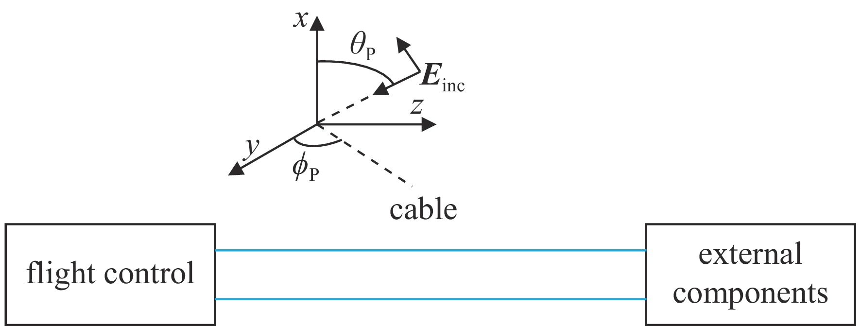
50Ω [13]。在无人机系统中,线缆场-路耦合模型可等效为一般电路模型,通过传输线方程[14-15]可求解在任意角度平面波激励下线缆场-路耦合瞬态响应,图3为无人机系统场-路耦合模型,图4为无人机系统场-路耦合等效电路模型。
由于辐照场的作用,在无人机场-路耦合模型中引入两个辐射源,得到等效电路模型如图4所示。
任意角度入射电磁场可表示为
Einc(x,y,z,t)=[exax+eyay+ezaz]E0(t−xvx−yvy−zvz) (1) vx=ωβx=−vcosθp (2) vy=ωβy=−vsinθpcosϕp (3) vz=ωβz=−vsinθpsinϕp (4) 根据传输线方程,可推导得到入射场激励信号表达式为
{V+(t)=d(ex+ez(Ld)Tx(TD−Tz))(E0(t−TD−Tx2)−E0(t−Tz−Tx2))V−(t)=d(ex−ez(Ld)Tx(TD+Tz))(E0(t+TD−Tx2)−E0(t−Tz−Tx2)) (5) 无人机系统线缆终端响应表达式为
{V(0,t)=RSRS+ZC(ΓL∞∑i=0αiV+(t−(2i+1)TD)−∞∑i=0αiV−(t−(2i+1)TD))V(L,t)=RLRL+ZC(∞∑i=0αiV+(t−(2i)TD)−ΓS∞∑i=0αiV−(t−(2i)TD)) (6) 式中:
TD=Lv ,RS 为始端阻抗,RL 为终端阻抗,ZC 为电路容性阻抗,α=ΓSΓL ,L为无人机线缆长度,Tx=Lvx ,Tz=Lvz ,ΓS=RS−ZCRS+ZC ,ΓL=RL−ZCRL+ZC ,公式(5)与公式(6)联立求得无人机系统场-路耦合终端响应。2. 无人机系统线缆电磁效应仿真分析
2.1 无人机线缆耦合仿真分析
在无人机多类型线缆场路联合仿真分析中,设置线缆为单芯线缆,线芯为直径0.5 mm的金属铜,外部由PVC绝缘层包裹,线缆的截面直径为1 mm,双芯线缆为两根单芯线缆并排放置,绞合线缆为两根单芯线缆按照20 mm旋转一圈设置,带状线为8根单芯线缆并排放置,线缆间隔为2.3 mm。
考虑实际情况下电磁干扰信号入射角度的随机性,仿真平面波入射场景,线缆长度为1 m,干扰信号为高斯宽带信号,传播矢量
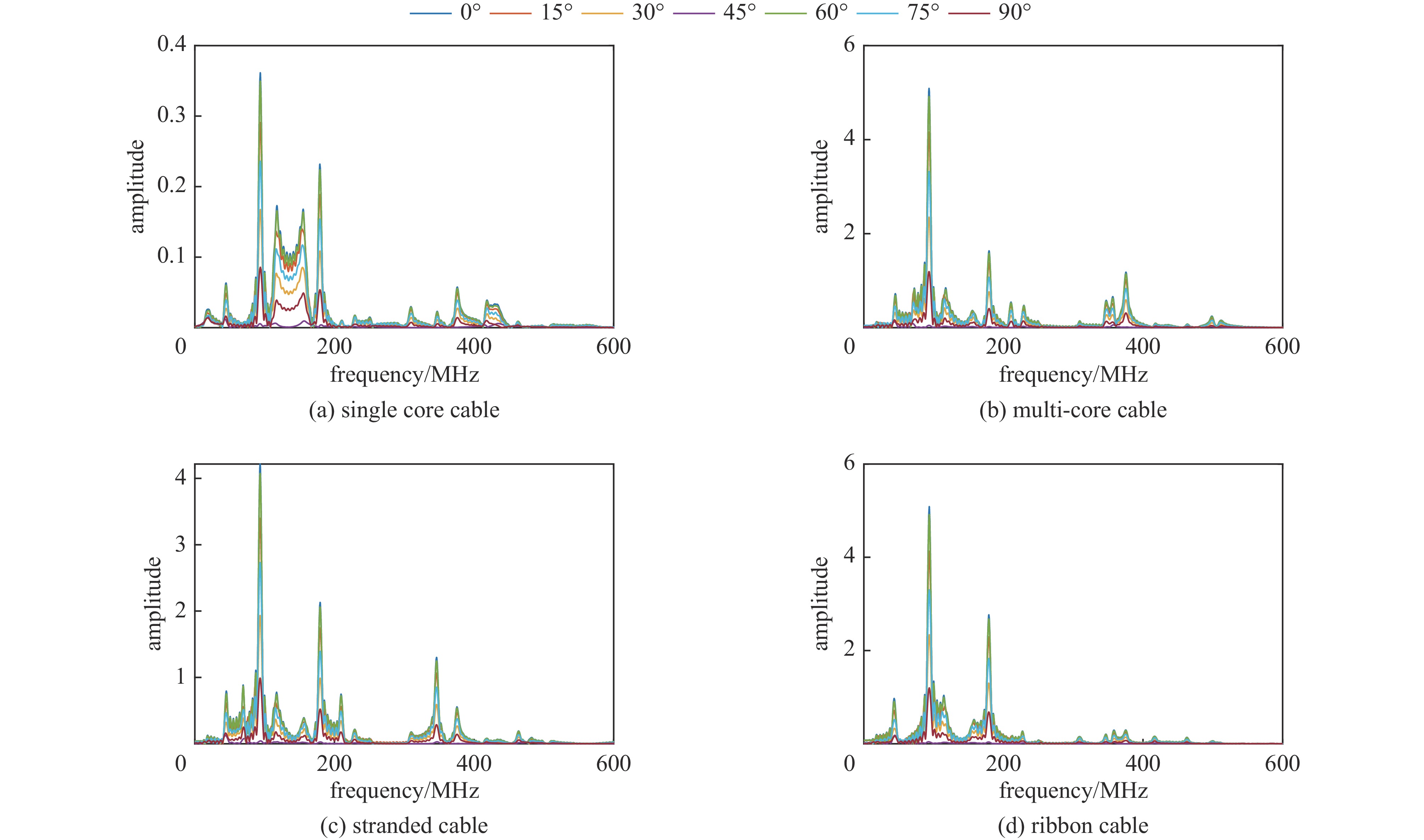
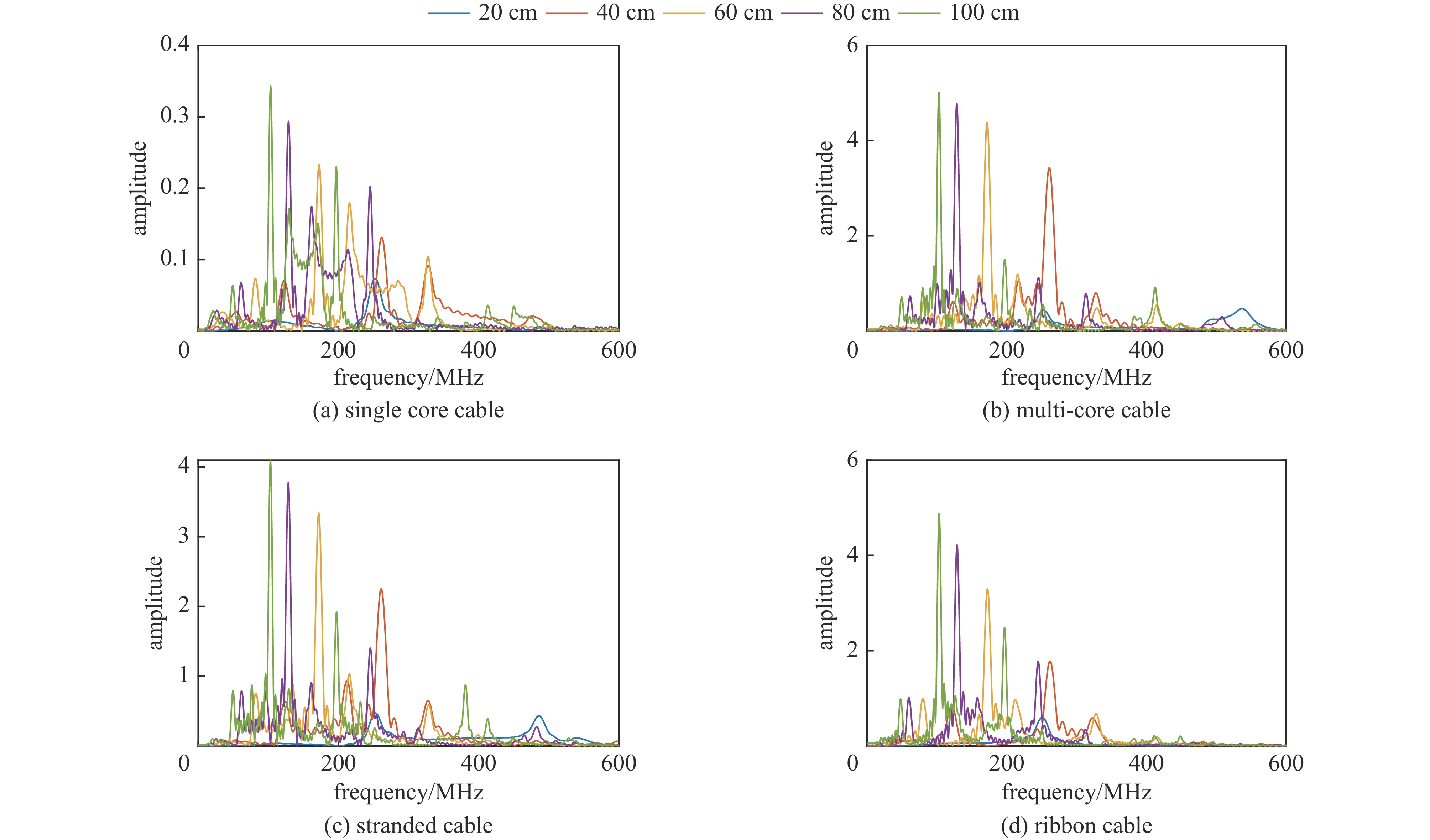
k=(0,0,−1) ,电场分量方向为e=(cosθ,sinθ,0) ,参数角θ 间隔15°进行参数扫描,表达式为f(t)=exp[−(t−0.0016)2/4] ,时域单位为μs,幅度为1 V,带宽为10−1 GHz,仿真结果如图5、图6所示。时域仿真结果表明,电场矢量与线缆所在平面平行时,耦合的峰值电压最大,其中单芯线缆直连的情况描述的是地到地的连接,因此感应电压较低,大小为0.016 V。其余三种情况均为常用的信号线的连接方式,如无人机外接导航定位模块采用的USART接口使用双绞线的N5-N6的连接方式。由于仿真的四种线缆均无屏蔽层,因此线缆端口处的感应电压较大,双芯线缆与双绞线缆感应电压峰值为0.14 V,带状线缆感应电压峰值为0.1 V。频域结果表明,不同类型长度相等的线缆谐振频点相同,1 m长线缆的谐振频点在100 MHz与200 MHz。根据传输线理论可知,线缆谐振频点与线缆长度有关。结合上述频域仿真结果,进一步研究耦合特征与线缆长度的关系:以20 cm为间隔,仿真分析长度20~100 cm的线缆耦合特征。考虑平面波正入射情况,传播矢量
k=(0,0,−1) ,电场矢量e=(1,0,0) ,干扰信号为高斯宽带信号,带宽为10−1 GHz,表达式为f(t)=exp[−(t−0.0016)2/4] ,时域单位为μs,幅度为1 V,仿真结果如图7所示。仿真结果表明,线缆耦合特性与线缆的长度密切相关,不同长度的线缆具有不同的频率谐振点:20 cm至100 cm长线缆谐振点分别为500 MHz、250 MHz、180 MHz、130 MHz、100 MHz,谐振频点的倒数与线缆长度满足相同的倍数关系,由于线缆长度过大,根据开路传输线的多谐性,在一个频段范围内可能出现多个谐振模式,导致多个谐振频点。
2.2 系统级线缆耦合仿真
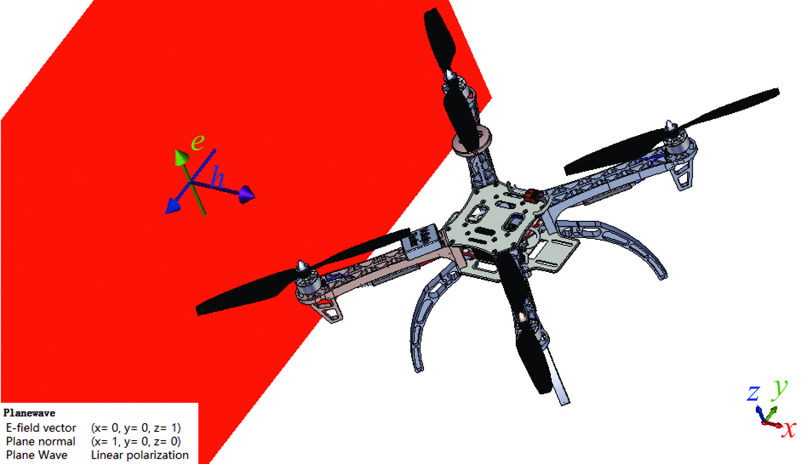
实际的无人机系统复杂的物理结构严重影响了无人机系统中的线缆耦合特征,通过建立四旋翼无人机模型对无人机系统级线缆耦合特征进一步进行研究[16],基于无人机系统实际的物理结构布置线缆,进而从宏观上分析系统线缆耦合薄弱环节。该模型基于主流开源无人机F450工程文件以最大程度还原实际工程情形,进一步删除不必要的物理结构以简化仿真的复杂度,并给定各结构对应材料参数。其中,线缆、顶部和底部结构电路板、电机设置为金属,其余部分设置为介质材料
(μ=1,ε=4.3) 。F450无人机三维仿真模型如图8所示。考虑平面波侧入射的场景,传播矢量
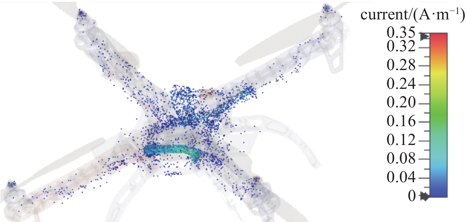
k=(−1,0,0) ,电场矢量e=(0,0,1) ,干扰信号为高斯宽带信号,信号表达式及参数设置与2.1小节一致,干扰信号带宽设置为10−1 GHz,仿真给出无人机系统表面电流分布情况如图9所示。仿真结果表明,金属线缆对电磁干扰具有强耦合性,表面电流集中分布在金属线缆表面;且在无人机飞控线缆端口处、旋翼线缆处电流集中。为确定无人机系统线缆耦合的薄弱环节,通过在飞控端口处、机翼线缆处、旋翼线缆处设置电压监测器,计算无人机各位置与底部结构电路板参考地之间的电压,进而得到无人机系统线缆耦合薄弱环节。电压监测器具体设置如图10所示。与所构建线缆电磁干扰场路联合仿真模型相比,实际的线缆布置需要与无人机共形,因此感应电压受电磁干扰信号传播方向、极化方向等诸多因素影响。因此,设置干扰信号为高斯信号,传播矢量为
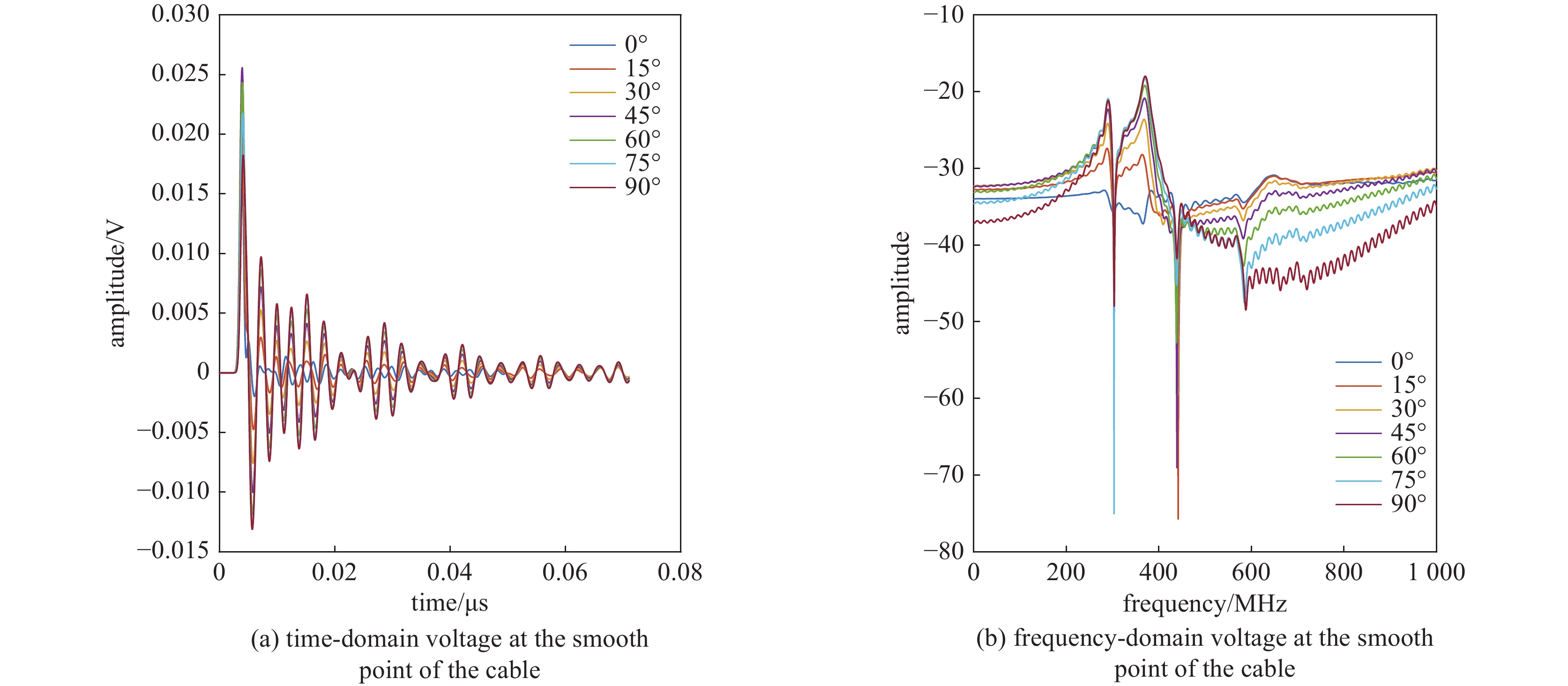
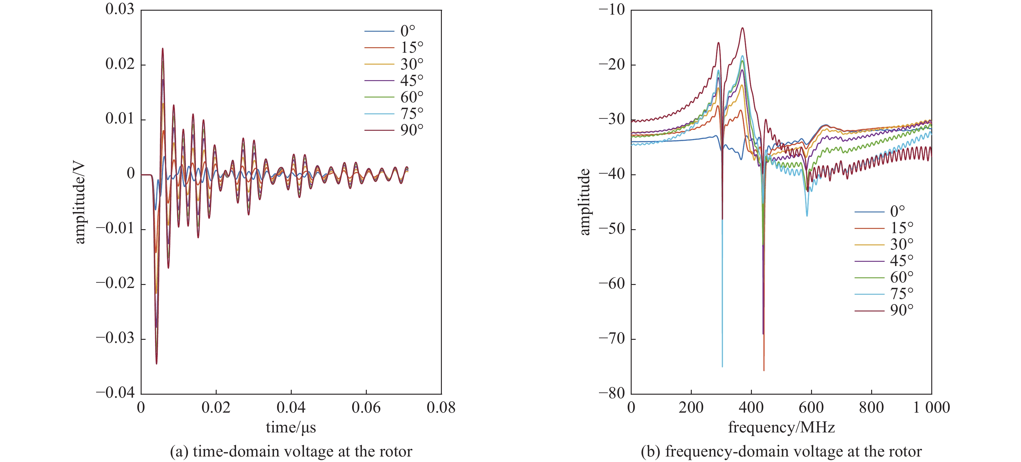
k=(1,0,0) ,电场分量方向为e=(0,sinθ,cosθ) ,同样选择电场矢量以参数角θ 间隔15°进行参数扫描,进而研究无人机系统级线缆耦合特征分布,得到无人机系统线缆耦合薄弱环节。仿真结果如图11、图12、图13所示:当干扰信号方向与线缆所在平面平行时,无人机系统线缆耦合电压峰值最大,在无人机飞控线缆端口处,耦合电压峰值最大为0.052 V,耦合敏感频段为300~600 MHz;在无人机机翼线缆处,耦合电压峰值最大为0.025 V,耦合敏感频段为300~430 MHz;在无人机旋翼线缆处,耦合电压峰值为0.023 V,耦合敏感频段为300~430 MHz处,根据仿真结果可知无人机系统在飞控线缆端口处耦合电压较大。
3. 总 结
本文构建了线缆电磁干扰场路联合仿真模型,对无人机系统的多类型线缆进行了仿真分析,并基于主流开源无人机F450工程文件,建立了无人机系统级线缆仿真模型,根据无人机系统表面电流分布情况,在无人机系统飞控线缆端口处、机翼线缆处、旋翼线缆处设置了三个监测点,进一步研究了无人机系统内部不同位置处线缆耦合特征,得到了辐照干扰下无人机系统内部不同位置处线缆耦合敏感频段,通过将三个监测器的电压分布情况对比,得到了无人机系统线缆耦合的薄弱环节。仿真结果表明,激励信号的入射角度对于线缆的耦合特征有较大影响,当激励信号以不同角度入射相同长度的线缆时,线缆在电场矢量与线缆方向平行时耦合的峰值电压最大,且不同类型线缆耦合敏感频点相同,当激励信号以相同角度入射不同长度线缆时敏感频点的倒数与线缆长度满足相同的倍数关系;在无人机系统中,在单位幅度平面波电场矢量与线缆所在平面平行时耦合峰值电压最大,在无人机飞控线缆端口处,耦合电压峰值最大为0.052 V,耦合敏感频段为300~600 MHz;在无人机机翼线缆处,耦合电压峰值最大为0.025 V,耦合敏感频段为300~430 MHz;在无人机旋翼线缆处,耦合电压峰值为0.023 V,耦合敏感频段为300~430 MHz,根据仿真结果可知无人机系统线缆耦合薄弱环节在飞控线缆端口处。
-
表 1 BRing二极铁电源样机设计参数
Table 1. Design parameters of BRing dipole-magnet power supply prototype
maximum current Imax/A maximum current rise rate ˙Imax/(A/s) load inductance LM/mH load resistor RM/mΩ > 3900 > 38000 116 36.4 表 2 磁场与励磁电流质量测量实验参数
Table 2. Test parameters of magnetic field and excitation current quality measurement
test parameter constant current excitation tests pulse excitation tests excitation current amplitude 400 A 3900 Arated magnetic field of dipole-magnet
deflection radius of dipole-magnet
deviation angle of dipole-magnet1.58 T
21.5 m
7.5°1.58 T
21.5 m
7.5°deflection angle of the magnetic coil 10.14° / effective area of the magnetic coil (sc) 0.017 m2 / number of turns of the magnetic coil (nc) 20 turns / sampling rate of ADC 200 kHz 100 kHz bits of ADC 24 bit 18 bit voltage range of ADC [−10, 10] V [−10, 10] V measuring current range of DCCT [0, 4000 ] A[0, 6000 ] Acurrent voltage ratio of DCCT 400 A/V 600 A/V -
[1] Yang J C, Xia J W, Xiao G Q, et al. High Intensity heavy ion Accelerator Facility (HIAF) in China[J]. Nuclear Instruments and Methods in Physics Research Section B: Beam Interactions with Materials and Atoms, 2013, 317: 263-265. doi: 10.1016/j.nimb.2013.08.046 [2] Zhou Xiaohong, Yang Jiancheng, The HIAF Project Team. Status of the high-intensity heavy-ion accelerator facility in China[J]. AAPPS Bulletin, 2022, 32: 35. doi: 10.1007/s43673-022-00064-1 [3] Zhang C. Status of BEPC and plans of BEPCII[C]//Proceedings of the 2nd Asian Particle Accelerator Conference. 2001. [4] Chen S Y, Xu H J, Zhao Z T. Shanghai synchrotron radiation facility[C]//Proceedings of the 1999 Particle Accelerator Conference. 1999: 209-211. [5] Hahn H, Forsyth E, Foelsche H, et al. The RHIC design overview[J]. Nuclear Instruments and Methods in Physics Research Section A: Accelerators, Spectrometers, Detectors and Associated Equipment, 2003, 499(2/3): 245-263. [6] Augustin I, on Behalf of the FAIR Project Coordination Group. Status of the FAIR project[J]. Nuclear Instruments and Methods in Physics Research Section B: Beam Interactions with Materials and Atoms, 2007, 261(1/2): 1014-1017. [7] High-Intensity Proton Accelerator Project Team. Accelerator technical design report for high-intensity proton accelerator facility project, J-PARC[R]. JAERI-Tech-2003-044, 2003. [8] Schmidt R. Status of the LHC[C]. IEEE Transactions on Nuclear Science, 2002. [9] Bruning O S, Collier P, Lebrun P, et al. LHC design Report[R]. Geneva: CERN, 2004. [10] Bordry F. LHC power converters performance requirements[R/OL]. https://cds.cern.ch/record/567166/files/7-5-fb.pdf. [11] Gerigk F. Superconducting RF at CERN: operation, projects, and R&D[J]. IEEE Transactions on Applied Superconductivity, 2018, 28: 3500205. [12] Liang Yiqing, Wang Xiaojun, Li Jiqiang, et al. IEEE 1588-based timing and triggering prototype for distributed power supplies in HIAF[J]. IEEE Transactions on Instrumentation and Measurement, 2022, 71: 5502309. [13] 胡寿松. 自动控制原理[M]. 北京: 科学出版社, 2001Hu Shousong. Principle of automatic control[M]. Beijing: Science Press, 2001 [14] Shen Yi, Tang Xiyuan, Shen Linxiao, et al. A 10-bit 120-ms/s SAR ADC with reference ripple cancellation technique[J]. IEEE Journal of Solid-State Circuits, 2020, 55(3): 680-692. doi: 10.1109/JSSC.2019.2946215 [15] Thurel Y, Bordy F, Charoy A. EMC concepts applied to the switching mode power converters supplying the superconductive magnets for the CERN LHC accelerator[C]//Proceedings of 2019 International Symposium on Electromagnetic Compatibility. 2019: 796-801. [16] Yang Xin, Yuan Ye, Zhang Xueqiang, et al. Shaping high-power IGBT switching transitions by active voltage control for reduced EMI generation[J]. IEEE Transactions on Industry Applications, 2015, 51(2): 1669-1677. doi: 10.1109/TIA.2014.2347578 [17] Jouyaeian A, Fan Qinwen, Zamparette R, et al. A hybrid magnetic current sensor with a multiplexed ripple-reduction loop[J]. IEEE Journal of Solid-State Circuits, 2023, 58(10): 2874-2882. doi: 10.1109/JSSC.2023.3273389 -


 下载:
下载:


 下载:
下载:


