Design of Ka band gyro-TWT high purity input structure
-
摘要: 为了实现Ka波段回旋行波管高纯度TE01模式输入,通过在输出口添加滤波结构,对二级功分TE01输入耦合器进行改进,改进后杂散模式传输效率由平均7%下降至2%。该结构主体为一个级联的两级Y型功分网络,能高效地实现矩形波导TE10模式到圆波导TE01模式的转换。在基于传输线理论对功分网络的传输性能理论分析的基础上,借助三维电磁仿真软件进行多次优化迭代,最终得到了一个在31 GHz附近模式转换效率大于99%的宽带TE01输入耦合器, 该输入耦合器具有5 GHz的−0.1 dB插入损耗带宽,同时有效频带内的平均模式转换效率高达98.6%,模式纯度在99%以上并且回波损耗小于−15 dB。采用矢量网络分析仪对该器件进行了背靠背冷测实验,结果表明,其带内衰减约为0.5 dB,与仿真计算结果偏差较小,符合工程实际需求。Abstract: To realize the high-purity TE01 mode input of the Ka-band cyclotron traveling wave tube, the two-stage power divider TE01 input coupler is improved by adding a filter structure at the output port, and the transmission efficiency of the spurious mode is reduced from the original average of 7% to less than 2%. The main body of the structure is a cascading two-stage Y-type power divider network, which can efficiently realize the conversion of rectangular waveguide TE10 mode to circular waveguide TE01 mode. Based on the theoretical analysis of transmission performance of power divider network based on transmission line theory, and with the help of 3D electromagnetic simulation software, several optimization iterations are carried out, and finally a wideband TE01 input coupler with mode conversion efficiency greater than 99% near the frequency of 31 GHz is obtained, the input coupling structure has a −0.1 dB insertion loss bandwidth of 5 GHz, and the average mode conversion efficiency in the effective frequency band is as high as 98.6%, the mode purity is 99% and the return loss is less than −15 dB. Back-to-back cold test experiments were carried out on the device using vector network analyzer, and the results show that the in-band attenuation is about 0.5 dB, which deviates little from the simulation calculation result, which meets the actual engineering requirements.
-
Key words:
- gyro-TWT /
- power distribution network /
- input coupling structure /
- broadband /
- filter structure /
- mode conversion
-
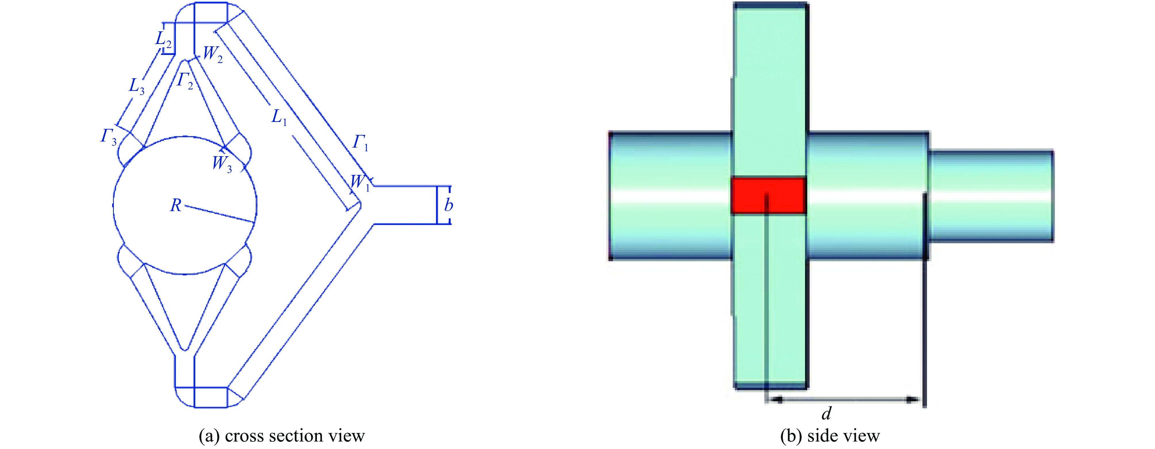
表 1 功分输入结构的最终结构参数
Table 1. Final structure parameter of power divider input structure
a/mm b/mm R/mm Rc/mm W1/mm W2/mm W3/mm L1/mm L2/mm L3/mm d/mm sheet metal size 7.112 3.556 6.41 4.57 1.78 0.90 3.0 22.9 3.00 12.1 3.556 2.24 mm×7.38 mm×0.5 mm 表 2 功分输入结构性能对比
Table 2. Comparison of power divider input structure performance
structure plug loss relative
bandwidth/%maximum mode conversion
efficiency/%mode
purity/%Qiao Yiming[7]. 220 GHz TE10-TE01 sidewall coupled mode converter. 1.0 dB bandwidth 6.8 99.0 − Yu C F[8]. High-performance circular TE01-mode converter. 1.0 dB bandwidth 18.2 98.5 99.0 Zhang Qiang[10]. Circular waveguide TE01 mode converter design. 0.1 dB bandwidth 6.6 99.9 − Sun Hao[9]. W-band cyclotron broad band low-loss input coupler design. 0.1 dB bandwidth10.5 99.8 96.8 structure of this work. 0.1 dB bandwidth 14.5 100.0 99.3 -
[1] 刘盛纲. 电子回旋脉塞和回旋管的进展[M]. 成都: 四川教育出版社, 1988Liu Shenggang. Progress of electronic cyclotron maser and cyclotron[M]. Chengdu: Sichuan Education Press, 1988 [2] 王丽, 鄢然, 蒲友雷, 等. 高功率毫米波回旋器件的需求及发展[J]. 真空电子技术, 2010(2):21-26 doi: 10.16540/j.cnki.cn11-2485/tn.2010.02.009Wang Li, Yan Ran, Pu Youlei, et al. Requirement and development of high power millimeter-wave gyrotron device[J]. Vacuum Electronics, 2010(2): 21-26 doi: 10.16540/j.cnki.cn11-2485/tn.2010.02.009 [3] Chu K R, Barnett L R, Lau W K, et al. A wide-band millimeter-wave gyrotron traveling-wave amplifier experiment[J]. IEEE Transactions on Electron Devices, 1990, 37(2): 1557-1560. [4] 鄢然. 磁控注入电子枪低频振荡分析及Ka波段回旋行波管研究[D]. 成都: 电子科技大学, 2010Yan Ran. The analysis of the low frequency oscillation in magnetic injection gun and research on Ka band gyrotron traveling wave tube[D]. Chengdu: University of Electronic Science and Technology of China, 2010 [5] 徐勇, 熊彩东, 罗勇, 等. Ka波段TE01模回旋行波管宽带输入耦合器的设计[J]. 真空科学与技术学报, 2012, 32(3):208-213 doi: 10.3969/j.issn.1672-7126.2012.03.06Xu Yong, Xiong Caidong, Luo Yong, et al. Design of broad-band input coupler of Ka-band TE01 mode gyro-TWT[J]. Chinese Journal of Vacuum Science and Technology, 2012, 32(3): 208-213 doi: 10.3969/j.issn.1672-7126.2012.03.06 [6] 徐寿喜, 刘濮鲲, 张世昌. Ka波段二次谐波回旋速调管放大器输入耦合器的分析与模拟[J]. 强激光与粒子束, 2004, 16:477-480Xu Shouxi, Liu Pukun, Zhang Shichang. Analysis and simulation of an input coupler for a Ka-band second harmonic gyroklystron amplifier[J]. High Power Laser and Particle Beams, 2004, 16: 477-480 [7] 乔益民, 兰峰. 220GHz TE10-TE01侧壁耦合模式转换器的研究[J]. 大众科技, 2013, 15(2):1-3 doi: 10.3969/j.issn.1008-1151.2013.02.002Qiao Yimin, Lan Feng. Investigation of 220GHz TE01-TE10 sidewall coupling mode converter[J]. Popular Science & Technology, 2013, 15(2): 1-3 doi: 10.3969/j.issn.1008-1151.2013.02.002 [8] Yu C F, Chang T H. High-performance circular TE01-mode converter[J]. IEEE Transactions on Microwave Theory and Techniques, 2005, 53(12): 3794-3798. doi: 10.1109/TMTT.2005.859866 [9] 孙昊, 李浩, 王峨锋, 等. W波段回旋管宽带低损耗输入耦合系统[J]. 强激光与粒子束, 2015, 27:053004 doi: 10.11884/HPLPB201527.053004Sun Hao, Li Hao, Wang Efeng, et al. Broad band low loss input coupling system in W-band gyrotron[J]. High Power Laser and Particle Beams, 2015, 27: 053004 doi: 10.11884/HPLPB201527.053004 [10] 张强, 袁成卫, 陈俊, 等. 圆波导TE01模激励器设计及实验研究[J]. 强激光与粒子束, 2018, 30:063033 doi: 10.11884/HPLPB201830.170462Zhang Qiang, Yuan Chengwei, Chen Jun, et al. Investigations on TE01 circular waveguide mode transducer[J]. High Power Laser and Particle Beams, 2018, 30: 063033 doi: 10.11884/HPLPB201830.170462 [11] Wu Zewei, Liao Xiaoyi, Wang Keqiang, et al. A circular TE02 mode generator with high purity for gyro-TWT study[J]. IEEE Microwave and Wireless Components Letters, 2020, 30(2): 137-140. doi: 10.1109/LMWC.2020.2966071 [12] 朱敏, 罗积润, 栾远涛, 等. 采用矩形到同轴扇形渐变TE10 □→TE01 ⊙模式变换器带宽特性的研究[J]. 电子与信息学报, 2007, 29(6):1508-1510Zhu Min, Luo Jirun, Luan Yuantao, et al. Bandwidth property of the converter with sector taper from a rectangular guide TE10 □ mode to a coaxial guide TE01 ⊙ mode[J]. Journal of Electronics & Information Technology, 2007, 29(6): 1508-1510 -


 下载:
下载:


