

Generation of sub-mm focal spot for intense-current accelerator utilizing spatial collimating restriction
-
摘要:
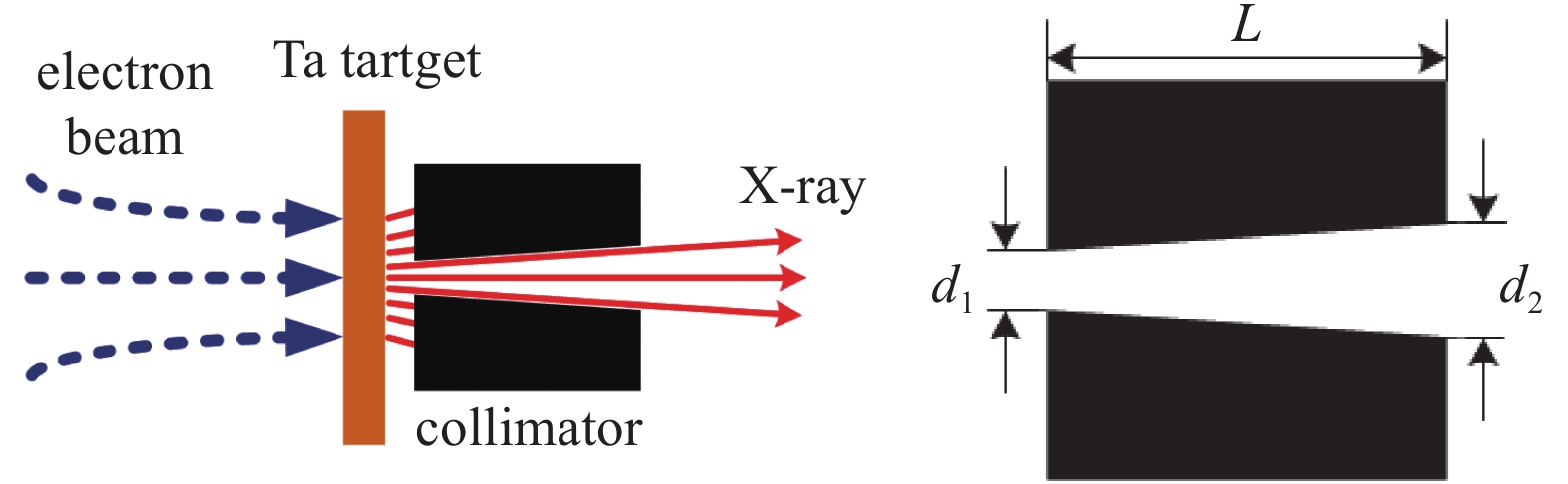
焦斑大小是评价加速器性能的关键指标之一,减小焦斑尺寸可以有效提高闪光照相中对客体成像的空间分辨能力。本文研究设计空间限束结构,减小加速器光源焦斑的有效尺寸降低成像几何模糊。采用蒙特卡罗方法对电子束打靶产生轫致辐射和光子穿过空间限束结构的成像过程进行模拟,分析采用不同空间限束结构时光源有效焦斑的分布及大小、光子角度分布和能谱分布等特征参数。理论计算结果表明,通过空间限束可以使强流加速器光源焦斑FWHM减小至亚毫米量级。
Abstract:Focal spot size is a key parameter for evaluating the resolving power of the accelerator. A reduction in the focal spot size can effectively improve the spatial resolution of the object. This work studies and designs collimator structures for spatial restriction, which help to reduce the geometry blur of imaging and thus obtain a smaller effective spot-size. The Monte Carlo method is applied to simulate the generation of the light source and the imaging process of the spatial restriction structures. The parameters of the light source with different collimator structures are analyzed, including the distribution and size of the effective focal spot, the angular distribution and the spectrum of the photons. Theoretical calculations show that an effective focal spot size with a sub-mm scale can be obtained by means of spatial restriction at the expense of a partial loss of the field-of-view and the exposure.
-

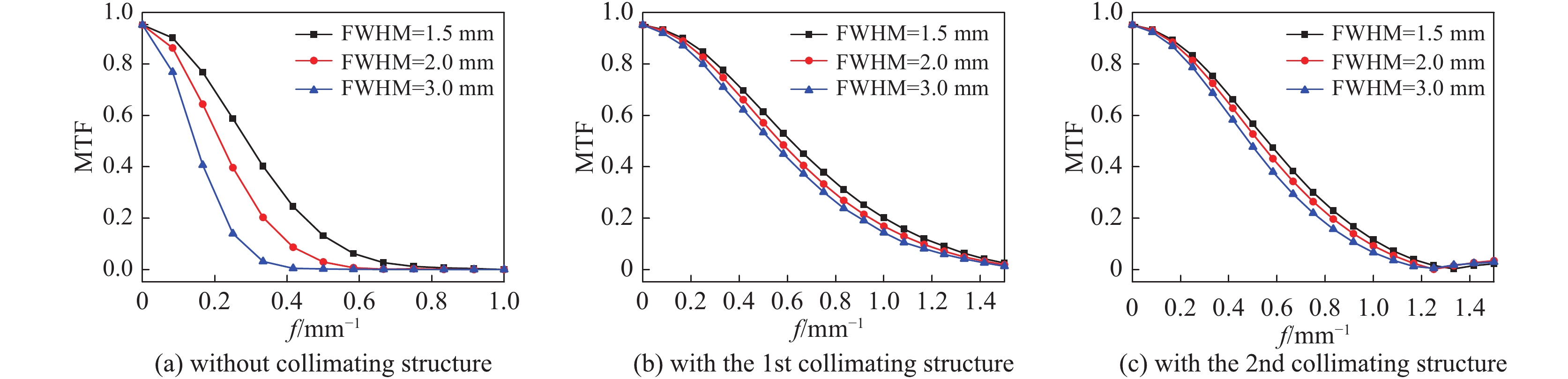
图 2 无准直体时光源焦斑分布
Figure 2. Spatial distribution of source spot without collimating structure
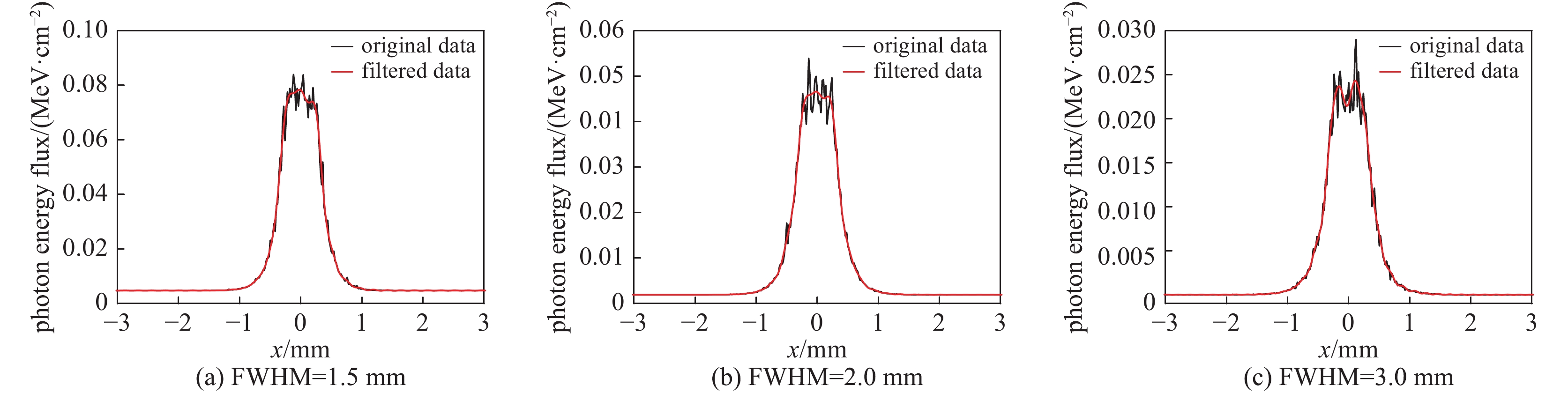
图 3 准直结构1条件下的光源焦斑分布
Figure 3. Spatial distribution of source spot with the 1st collimating structure
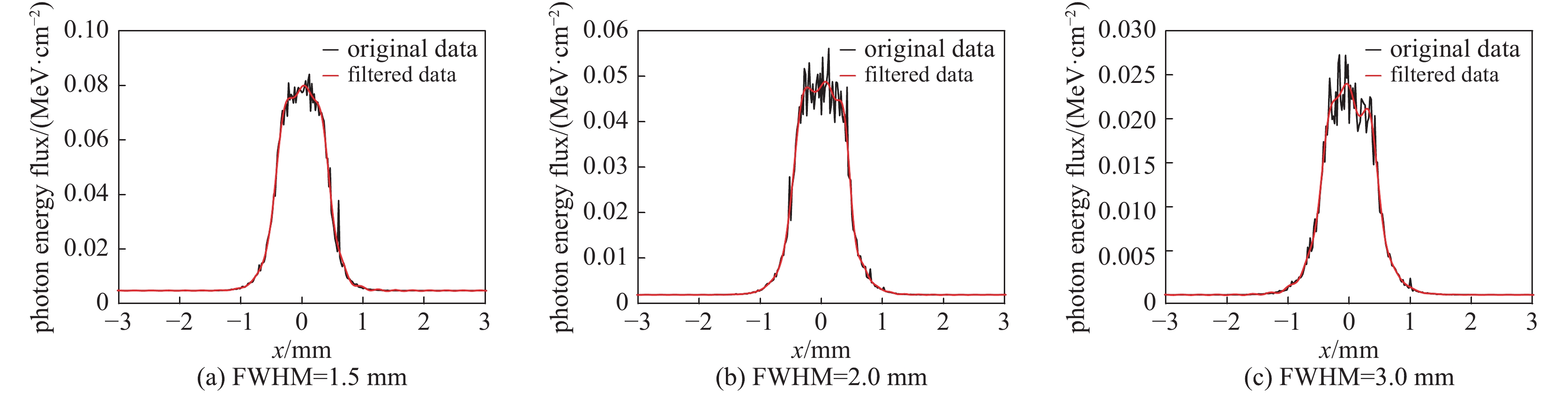
图 4 准直结构2条件下的光源焦斑分布
Figure 4. Spatial distribution of source spot with the 2nd collimating structure
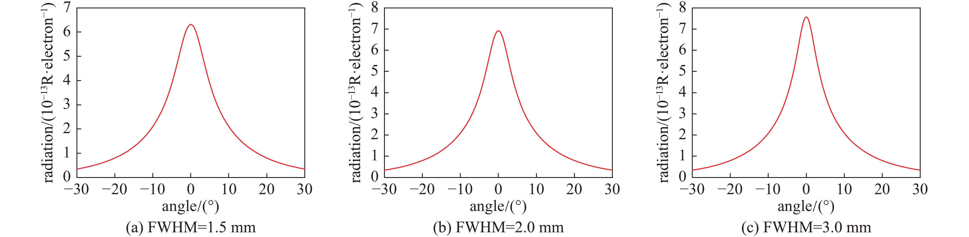
图 6 无准直体时光源照射量角度分布
Figure 6. Angular distribution of the light source radiation without collimating structure
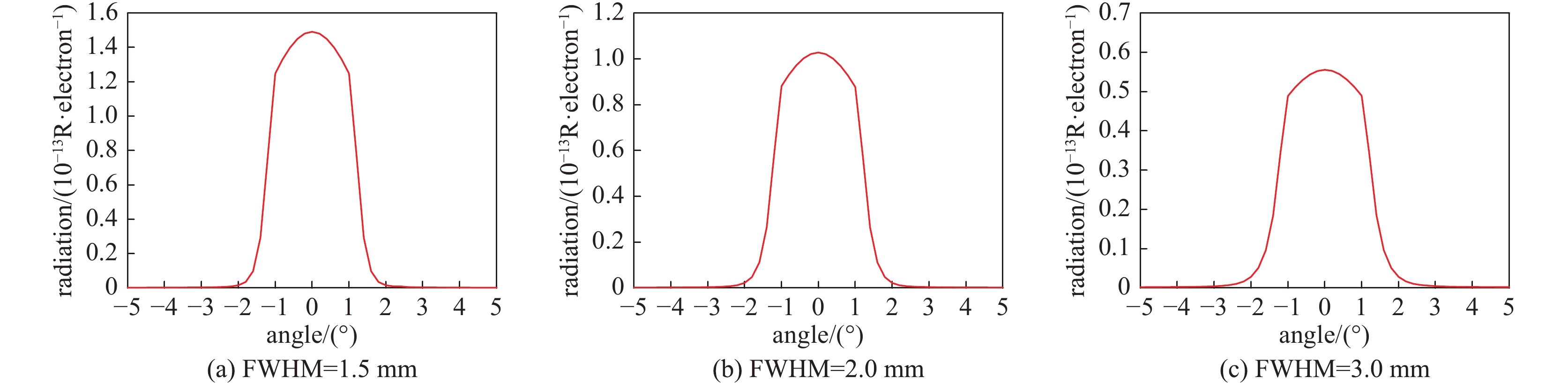
图 7 限束结构1条件下的光源照射量角度分布
Figure 7. Angular distribution of the light source radiation with the 1st collimating structure
图 8 限束结构2条件下的光源照射量角度分布
Figure 8. Angular distribution of the light source radiation with the 2nd collimating structure
图 9 无准直体时正前方光子数量谱分布
Figure 9. Photon spectra at straight forward direction without collimating structure
图 10 准直结构1条件下正前方光子数量谱分布
Figure 10. Photon spectra at straight forward direction with the 1st collimating structure
图 11 准直结构2条件下正前方光子数量谱分布
Figure 11. Photon spectra at straight forward direction with the 2nd collimating structure
表 1 有无限束结构条件下的光源焦斑尺寸
Table 1. Comparison of light source spot size between imaging processes with and without collimating structures
collimating structure FWHM of electron beam /mm FWHM of light source/mm f50%MTF/mm-1 D50%MTF/mm D50%MTF /FWHM without collimating structure 1.50 1.52 0.30 2.39 1.56 2.00 1.98 0.22 3.18 1.61 3.00 3.05 0.16 4.45 1.45 the 1st collimating structure 1.50 0.66 0.64 1.10 1.50 2.00 0.68 0.59 1.19 1.60 3.00 0.71 0.56 1.27 1.66 the 2nd collimating structure 1.50 0.85 0.58 1.21 1.34 2.00 0.89 0.54 1.30 1.35 3.00 0.92 0.50 1.41 1.47  下载: 导出CSV
表 2 有无限束结构条件下的光源照射量分布
Table 2. Comparison of light source radiation between imaging processes with and without collimating structures
collimating
structureFWHM of electron
beam /mmmaximum of exposure/
(10−13R/electron)emitting angle at half maximum
of exposure /(°)photon number flux /
(10−4cm−2·electron−1)average photon
energy /MeVwithout collimating structure 1.50 6.31 6.55 6.33 3.06 2.00 6.92 5.81 6.90 3.08 3.00 7.56 5.17 7.52 3.09 the 1st collimating structure 1.50 1.48 1.21 1.28 3.61 2.00 1.02 1.24 0.87 3.65 3.00 0.55 1.28 0.46 3.69 the 2nd collimating structure 1.50 2.02 1.26 1.80 3.46 2.00 1.42 1.29 1.25 3.52 3.00 0.77 1.32 0.67 3.57
下载: 导出CSV
-
[1] Boyd T J, Rogers B T, Tesche R R, et al. PHERMEX—A high-current electron accelerator for use in dynamic radiography[J]. Rev Sci Instrum, 1965, 36: 1401-1408. doi: 10.1063/1.1719343 [2] Scarpetti R D, Boyd J K, Earley G G, et al. Upgrades to the LLNL flash X-ray induction linear accelerator (FXR)[C]//11th IEEE International Pulsed Power Conference — Digest of Technical Papers. 1997, 1/2: 597–602. [3] 邓建军, 丁伯南, 王华岑, 等. “神龙一号”直线感应加速器物理设计[J]. 强激光与粒子束, 2003, 15(5):502-504. (Deng Jianjun, Ding Bonan, Wang Huacen, et al. , Physical design of the Dragon-I linear induction accelerator[J]. High Power Laser and Particle Beams, 2003, 15(5): 502-504 [4] 施将君. 高能闪光照相引论[M]. 北京: 国防工业出版社, 1997.Shi Jiangjun. Introduction of high-energy flash radiography[M]. Beijing: National Defence Industry Press, 1997 [5] Briesmeister J F. MCNP – A general Monte Carlo N-particle transport code – Version 4C[R]. LA-13709-M, 2000. [6] Agostinelli S, Allison J, Amako K, et al. Geant4 – a simulation toolkit[J]. Nuclear Instruments and Methods in Physics Research Section A – Accelerators Spectrometers Detectors and Associated Equipment, 2003, 506(3): 250-303. [7] Kawrakow I, Rogers D W O. The EGSncr code system: Monte Carlo simulation of electron and photon transport[R]. Ottawa: National Research Council of Canada, 2002. [8] 王毅, 李勤, 代志勇. 蒙特卡罗模拟分析电子束发射度对照射量空间分布影响[J]. 强激光与粒子束, 2017, 29:065006. (Wang Yi, Li Qin, Dai Zhiyong. Analysis on influence of beam emittance on spatial distribution of exposure using Monte Carlo simulation[J]. High Power Laser and Particle Beams, 2017, 29: 065006 doi: 10.11884/HPLPB201729.170029 [9] Muller K H. Measurement and characterization of X-ray spot size[R]. LA-UR-89-1886, 1989. [10] Ekdahl C. Characterizing flash-radiography source spots[J]. Journal of the Optical Society of America A, 2011, 28(12): 2501-2509. doi: 10.1364/JOSAA.28.002501 -

 点击查看大图
计量
- 文章访问数: 1453
- HTML全文浏览量: 562
- PDF下载量: 133
- 被引次数: 0
