

-
摘要: 磁化套筒惯性聚变(MagLIF)构型可充分利用现有大型脉冲功率驱动装置,如聚龙一号等。基于磁流体力学方程组和1∶1比例氘氚(DT)混合燃料聚变模型,开发了零维MagLIF数值模拟程序并进行了初步探索研究。计算结果表明初始负载参数(如轴向磁场强度,预加热温度、时刻,负载半径等)与聚变产额之间有着密切的联系,在给定条件下,可依据计算给出的定性关系进行负载优化设计。值得注意的是,根据计算结果,即使在理想条件下,氘氚燃料要实现能量收支平衡,则驱动器的电流必须大于21.2 MA。这意味着聚龙一号装置(10 MA)无法开展集成化的MagLIF实验,进一步的校验计算验证了上述观点,并在此基础上提出铝套筒分解实验的建议和负载设计参数。所取得的计算结果有利于加深对MagLIF套筒压缩阶段物理过程的认知和理解。Abstract: Magnetized Liner Inertial Fusion (MagLIF) concept has promising potentials for future energy source (Phys.Plasmas, 2014, 21:072711), it is widely applicable to large-scale pulsed power generators such as the Primary Test Stand (PTS) facility (10 MA, 100 ns). In this context, we’ve developed a zero-dimensional (0D) MagLIF simulation code basing on magneto-hydrodynamic (MHD) equations and Deuterium-Tritium (DT) fusion models. Relationships between fusion products and initial setups (magnetic field Bz0, preheat temperature T0 and so on) are explored using this code, results show optimal parameters existing under given inputs, which are very helpful for future experimental designs. Specifically, according to our simulations, critical driving current (>21.2 MA) is essential for fuel (50∶50 DT) energy to reach breakeven, which infers that PTS facility may not be suitable for integrated MagLIF experiments. Series of calculations are performed to confirm this inference, and more practical aluminum liner experiments are proposed and designed.
-
Key words:
- Magnetized Liner Inertial Fusion /
- PTS facility /
- MHD simulation /
- feasibility analysis
-
Figure 2. Demonstration of curves used in calculations: current curve from Ref.[13], trajectory of inner surface of liner, and time of laser preheat
Figure 3. Curves of fusion parameters Br, temperature and pressure evolving with time calculated by MagLIF-0D
Figure 4. Schematics of calculated results from MagLIF-0D code; (a) fusion yield and internal energy, (b) energy power transport evolving as initial axial field increases
Figure 5. Schematics of calculated results from MagLIF-0D code: (a) fusion yield and internal energy, (b) energy power transport evolving as preheat temperature increases
Figure 8. Schematic of fusion and internal energy curves evolved with liner aspect ratio (AR)

Figure 9. Schematic of fusion yield and internal energy curves evolved with initial liner outer radius (R0)
Figure 10. Schematic of six current curves used as input driving sources in MagLIF-0D code
Figure 11. Schematic of fusion and internal energy curves evolving with maximum driving current

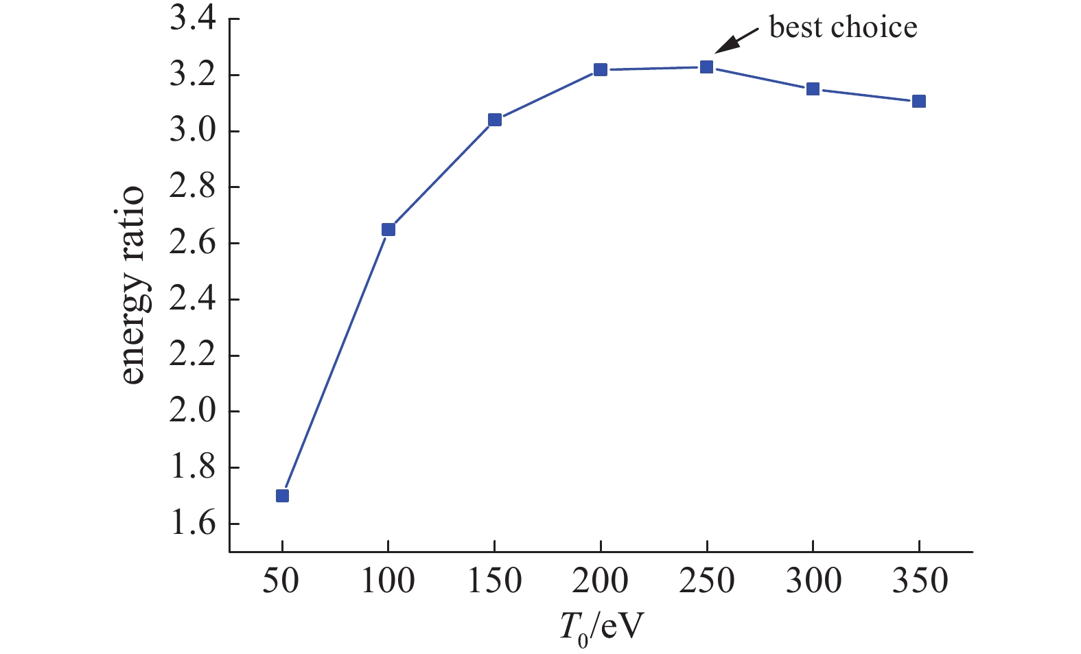
Figure 12. Schematic of energy gain (fusion yield divided by fuel internal energy) evolving with maximum driving current
Figure 13. Schematic of different current curves used to explore feasibility of MagLIF on PTS facility
Table 1. Comparisons between results calculated by MagLIF-0D, LASNEX and HYDRA codes
code density/(g/cm3) temperature/keV magnetic field/T compression ratio peak pressure/(1014 Pa) fusion yield/kJ LASNEX 0.5 8 13 500 23 3 500 MagLIF-0D 0.55 7.5 4 000 15 3 400 HYDRA 1.0 6−8 8 000−10 000 22 5 560  下载: 导出CSV
Table 2. Comparison between results calculated by MagLIF-0D code with different magnetizing fields
Bz0/T yield/(kJ/cm) Efuel/(kJ/cm) GpdV/(TW/cm) Gα/(TW/cm) Lrad/(TW/cm) Lcond/(TW/cm) ρ/(g/cm3) CR Bf/103T T/keV 0 93 124 162 13.5 49.2 126.00 3.00 32.0 0 2.2 10 677 387 183 123 21.3 6.00 0.69 15.0 1.6 6.7 20 790 425 183 138 18.9 1.50 0.58 14.0 2.7 7.3 30 807 432 180 137 17.9 0.60 0.55 13.5 3.9 7.5 40 805 435 180 135 17.4 0.38 0.53 13.5 5.0 7.5 50 768 438 174 125 17.0 0.24 0.51 13.0 6.0 7.4 60 710 415 164 112 16.0 0.15 0.49 12.5 7.0 7.2
下载: 导出CSV
Table 3. Comparisons between results calculated by MagLIF-0D code with different preheat temperatures
T0/eV yield/(kJ/cm) Efuel/(kJ/cm) GpdV/(TW/cm) Gα/(TW/cm) Lrad/(TW/cm) Lcond/(TW/cm) ρ/(g/cm3) CR Bf/103T T/keV 50 85 123 88.7 20.0 41.0 1.10 2.34 28.0 9.8 2.1 100 265 230 141.0 55.5 28.9 0.86 1.00 20.0 6.8 4.0 150 456 312 162.0 90.0 24.0 0.73 0.86 17.0 5.5 5.4 200 644 380 174.0 120.0 20.5 0.67 0.68 15.0 4.6 6.5 250 807 432 180.0 137.0 17.9 0.60 0.55 13.5 3.9 7.5 300 945 475 181.0 146.0 15.6 0.62 0.46 12.4 3.4 8.2 350 1087 517 182.0 157.0 14.1 0.62 0.40 11.5 3.0 9.0
下载: 导出CSV
Table 4. Comparisons between results calculated by MagLIF-0D code with different preheat time
theat/ns yield/(kJ/cm) Efuel/(kJ/cm) GpdV/(TW/cm) Gα/(TW/cm) Lrad/(TW/cm) Lcond/(TW/cm) ρ/(g/cm3) CR Bf/103T T/keV 0 545 358 152 85.3 16.8 0.6 0.565 13.73 4 6.2 43.8 720 408 180 119 17.7 0.65 0.562 13.68 4 7 69.3 807 432 180 137 17.9 0.6 0.55 13.5 3.9 7.5 87.7 573 360 143 90 17.5 0.65 0.587 13.98 4 6.3 98.6 330 266 108 48.4 18.1 0.76 0.71 15.39 4.4 4.6
下载: 导出CSV
Table 5. Comparisons between results calculated by MagLIF-0D code with different aspect ratio (AR)
AR yield/(kJ/cm) Efuel/(kJ/cm) GpdV/(TW/cm) Gα/(TW/cm) Lrad/(TW/cm) Lcond/(TW/cm) ρ/(g/cm3) CR Bf/103T T/keV 2 182 108 21.4 13.4 3.9 0.5 0.4 11.5 3.3 5.2 4 602 316 102 75.4 12.5 0.6 0.5 12.9 3.6 6.7 6 807 432 180 137 17.9 0.6 0.55 13.5 3.9 7.5 8 778 475 227 150 19.6 0.6 0.55 13.5 3.8 7.5 10 687 487 254 141 19.8 0.6 0.53 13.3 3.7 7.2
下载: 导出CSV
Table 6. Comparisons between results calculated by MagLIF-0D code with different initial liner radius
R0/mm yield/(kJ/cm) Efuel/(kJ/cm) GpdV/(TW/cm) Gα/(TW/cm) Lrad/(TW/cm) Lcond/(TW/cm) ρ/(g/cm3) CR Bf/103T T/keV 2.1 490 286 179 120 13 0.8 0.63 14.5 4.2 8.2 2.4 712 373 200 153 16.5 0.76 0.62 14.3 4.1 8.2 2.7 807 432 180 137 17.9 0.6 0.55 13.5 3.9 7.5 3.0 631 426 124 72.5 15.6 0.54 0.43 12 3.2 6.0 3.3 322 364 54.2 17.1 10.3 0.4 0.26 9.4 2.0 3.8
下载: 导出CSV
Table 7. Comparisons between results calculated by MagLIF-0D code with different driving current
Imax/MA yield/(kJ/cm) Efuel/(kJ/cm) GpdV/(TW/cm) Gα/(TW/cm) Lrad/(TW/cm) Lcond/(TW/cm) ρ/(g/cm3) CR Bf/103T T/keV 20 203 244 55.6 16.5 7.6 0.5 0.31 10.1 2.1 4.2 27 807 432 180 137 17.9 0.6 0.55 13.5 3.9 7.5 35 2490 708 394 696 32 0.8 0.8 16.3 5.7 12.3 40 4800 965 564 1674 42.2 0.97 0.93 17.6 6.7 16.7 45 9776 1393 744 3900 52.2 1.1 1.05 18.7 7.6 24 50 35790 3128 907 12850 61.3 1.3 1.14 19.5 8.3 54
下载: 导出CSV
Table 8. Calculated results by MagLIF-0D code with different parameters using method of exhaustion
B0/T T0/eV ρ0/(mg/cm3) R0/mm AR Q/% yield(kJ/cm) Efuel(kJ/cm) ρ(g/cm3) CR Bf/103T T/keV 30 250 3 1.64 6 18.3 7.9 43.2 0.14 6.9 0.84 2 10 150 3 1.64 6 13.8 3.8 27.5 0.33 10.5 0.51 1.3 30 250 1.5 1.64 6 27 9.45 35 0.12 8.8 1.2 3.3 30 250 1.5 1.64 4 24.1 5.6 23.2 0.10 8.3 0.96 2.7 30 250 1.5 1.64 8 26.2 11.2 42.7 0.12 9.2 1.38 3.6 30 250 1.5 1.64 10 24.6 11.6 47.1 0.13 9.4 1.4 3.8 30 250 1.5 1.8 6 24.1 8.9 37 0.1 8 1.03 2.9 30 250 1.5 1.5 6 29.1 9.4 32.3 0.14 9.6 1.4 3.6 30 250 1.5 1.2 6 28.3 6.5 23 0.18 10.9 1.6 4 30 250 1.5 1.56 6 28.3 9.55 33.7 0.13 9.3 1.3 3.5 30 250 1.0 1.56 6 33 9.37 28.4 0.11 10.5 1.5 4.4 30 250 1.0 1.56 6 35 14 39.6 0.16 10.3 1.61 4.1
下载: 导出CSV
-
[1] Aymar R. The ITER project[J]. IEEE Trans Plasma Science, 1997, 6: 1187. [2] Shimomura Y, Spears W. Review of the ITER project[J]. IEEE Trans Plasma Science, 2004, 14: 1369. [3] Huang Chuanjun, Li Laifeng. Magnetic confinement fusion: A brief review[J]. Front Energy, 2018, 12: 305. doi: 10.1007/s11708-018-0539-1 [4] Hurricane O A, Springer P T, Patel P K, et al. Approaching a burning plasma on the NIF[J]. Phys Plasmas, 2019, 26: 052704. doi: 10.1063/1.5087256 [5] McCrory R L, Meyerhofer D D, Betti R, et al. Progress in direct-drive inertial confinement fusion[J]. Phys Plasmas, 2008, 15: 055503. doi: 10.1063/1.2837048 [6] Mordecai D R, Meyerhofer1 D D, Betti R, et al. The physics issues that determine inertial confinement fusion target gain and driver requirements: A tutorial[J]. Phys Plasmas, 1999, 6: 1690. doi: 10.1063/1.873427 [7] Thio Y C F, Panarella E, Knupp C E, et al. Magnetized target fusion in a spheroidal geometry with standoff drivers[C]//The 2nd Conference on Current Trends in International Fusion Research. 1999: 113. [8] Parks P B. On the efficacy of imploding plasma liners for magnetized fusion target compression[J]. Phys Plasmas, 2008, 15: 062506. doi: 10.1063/1.2948346 [9] Cassibry J T, Stanic M, Hsu S C, et al. Tendency of spherically imploding plasma liners formed by merging plasma jets to evolve toward spherical symmetry[J]. Phys Plasmas, 2012, 19: 052702. doi: 10.1063/1.4714606 [10] Schoenberg K F, Siemon R E. Magnetized target fusion: A proof-of-principle research proposal[R]. LA-UR-98-2413,1998. [11] Kirkpatrick R C. Magnetized target fusion (MTF) principle status and international collaboration[C]//Latin America Workshop on Plasma Physics. 1998. [12] Lindemuth I R, Kirkpatrick R C. Parameter space for magnetized fuel targets in inertial confinement fusion[J]. Nucl Fusion, 1983, 23: 263. doi: 10.1088/0029-5515/23/3/001 [13] Slutz S A, Herrmann M C, Vesey R A, et al. Pulsed-power-driven cylindrical liner implosions of laser preheated fuel magnetized with an axial field[J]. Phys Plasmas, 2010, 17: 056303. doi: 10.1063/1.3333505 [14] Slutz S A, Roger A V. High-gain magnetized inertial fusion[J]. Phys Rev Lett, 2012, 108: 025003. doi: 10.1103/PhysRevLett.108.025003 [15] McBride R D, Martin M R, Lemke R W, et al. Beryllium liner implosion experiments on the Z accelerator in preparation for magnetized liner inertial fusion[J]. Phys Plasmas, 2013, 20: 056309. doi: 10.1063/1.4803079 [16] Gomez M R, Slutz S A, Sefkow A B, et al. Experimental demonstration of fusion-relevant conditions in magnetized liner inertial fusion[J]. Phys Rev Lett, 2014, 113: 155003. doi: 10.1103/PhysRevLett.113.155003 [17] Awe T J, Jennings C A, McBride R D, et al. Modified helix-like instability structure on imploding z-pinch liners that are preimposed with a uniform axial magnetic field[J]. Phys Plasmas, 2014, 21: 056303. doi: 10.1063/1.4872331 [18] Sefkow A B, Slutz S A, Koning J M, et al. Design of magnetized liner inertial fusion experiments using the Z facility[J]. Phys Plasmas, 2014, 21: 072711. doi: 10.1063/1.4890298 [19] McBride R D, Slutz S A. A semi-analytic model of magnetized liner inertial fusion[J]. Phys Plasmas, 2015, 22: 052708. doi: 10.1063/1.4918953 [20] Feng Shuping, Li Hongtao, Xie Weiping, et al. Development of prototype module of Z-pinch primary test stand[J]. High Power Laser and Particle Beams, 2009, 21(3): 463-467. [21] Zhao Hailong, Deng Jianjun, Wang Ganghua, et al. Load optimal design for a primary test stand facility based on a zero-dimensional load model[J]. Chinese Phys B, 2011, 20: 105201. doi: 10.1088/1674-1056/20/10/105201 [22] Deng Jianjun, Wang Meng, Xie Weiping, et al. Super-power repetitive Z-pinch driver for fusion-fission reactor[J]. High Power Laser and Particle Beams, 2014, 26: 100201. doi: 10.3788/HPLPB20142610.100201 [23] Zhao Hailong, Zhang Hengdi, Wang Ganghua, et al. Design and verification of 1D magnetized linear inertial fusion simulation code[J]. High Power Laser and Particle Beams, 2017, 29: 072001. doi: 10.11884/HPLPB201729.170002 [24] Freidberg J. Plasma Physics and fusion energy[M]. Beijing: Science Press, 2010. [25] Basko M M, Kemp A J, Meyer-ter-Vehn J. Ignition conditions for magnetized target fusion in cylindrical geometry[J]. Nuclear Fusion, 2000, 40: 59-68. doi: 10.1088/0029-5515/40/1/305 -


 点击查看大图
计量
- 文章访问数: 1842
- HTML全文浏览量: 661
- PDF下载量: 84
- 被引次数: 0
