

Design of depressed collector for Ka-band extended interaction klystron
-
摘要: 为满足无线传能系统对高效率大功率毫米波功率源的迫切需求,开展大功率连续波速调管高效率技术研究,采用降压收集极技术实现速调管在效率上的有效提升。主要介绍了某Ka波段大功率连续波分布作用速调管(EIK)降压收集极的设计方案,包括注-波互作用后废电子能量分布及行为特性的研究,收集极初始条件、结构及电极电压的设计,给出了单级降压收集极和两级降压收集极的设计和计算结果。三维粒子模拟(PIC)计算结果表明,该Ka波段连续波EIK采用单级降压收集极时回收效率为41.0%,采用两级降压收集极时回收效率为68.8%,EIK总管效率相比于未采用降压收集极技术时的27.5%上升至54.8%,表明通过降压收集极技术可有效提升毫米波大功率速调管工作效率。Abstract: To meet the needs of the wireless transfer system for the high-efficiency high-power millimeter wave power source, the high-efficiency technology research of high-power continuous wave klystron was carried out, and the efficiency of the klystron was effectively improved by using the depressed-collector technology. This paper mainly introduces the design scheme of the depressed collector of a Ka-band high-power CW extended interaction klystron (EIK), including the investigation of electron energy distribution and behavior characteristics, the setting of the initial condition, the structure and the setting of the electrode voltage of the collector, and the design and calculation results of a single-stage depressed collector and a two-stage depressed collector for this high-power EIK. The results of PIC show that the recovery efficiency of the EIK with single-stage and two-stage depressed collector are 41% and 68.8% respectively, the net power conversion efficiency of this EIK is raised from a base value of 27.5% to 54.8% by using a two-stage depressed collector, which shows that it is feasible to improve the efficiency of high-power klystron by adopting the depressed collector technology.
-
Key words:
- extended interaction klystron /
- depressed collector /
- Ka-band /
- efficiency /
- 3D simulation
-
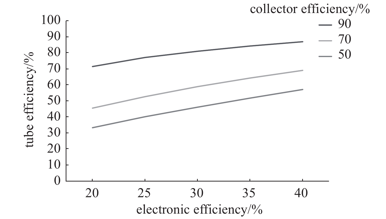
图 1 总效率和电子效率、收集极效率的关系
Figure 1. Relationship between tube efficiency, electronic efficiency and collector efficiency
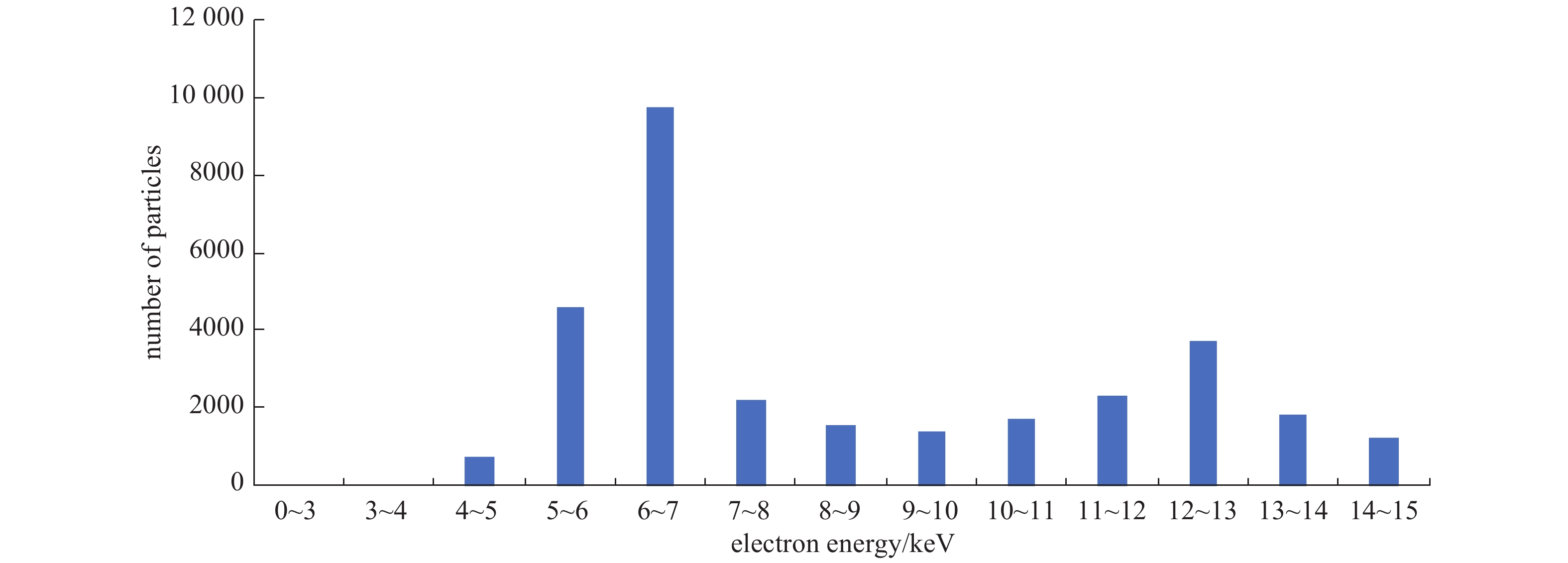
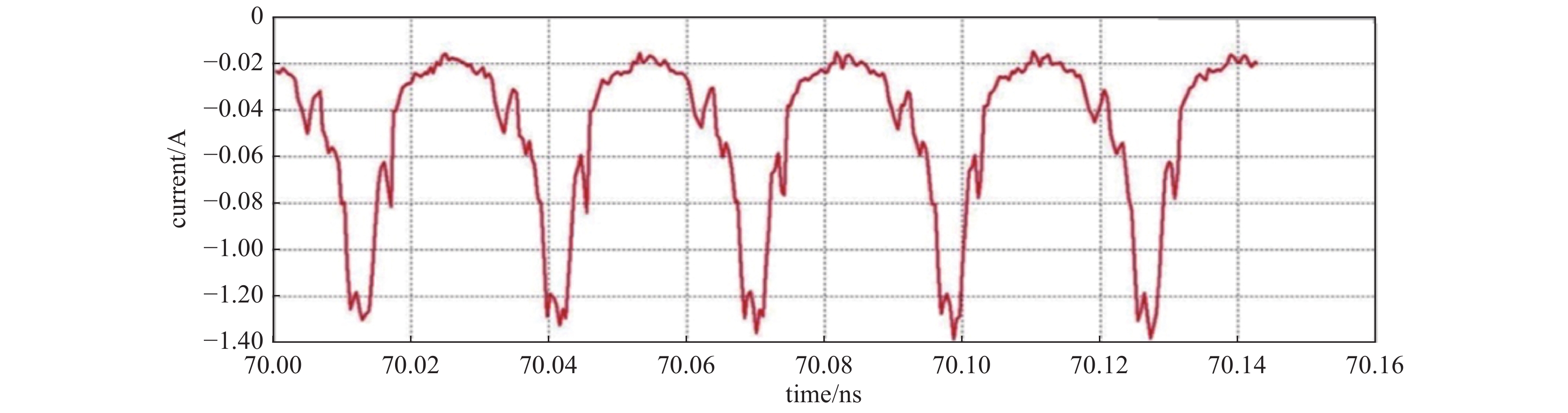
图 4 一个射频周期内携带不同能量的粒子数目统计图
Figure 4. Number of particles carrying different energy in one RF cycle
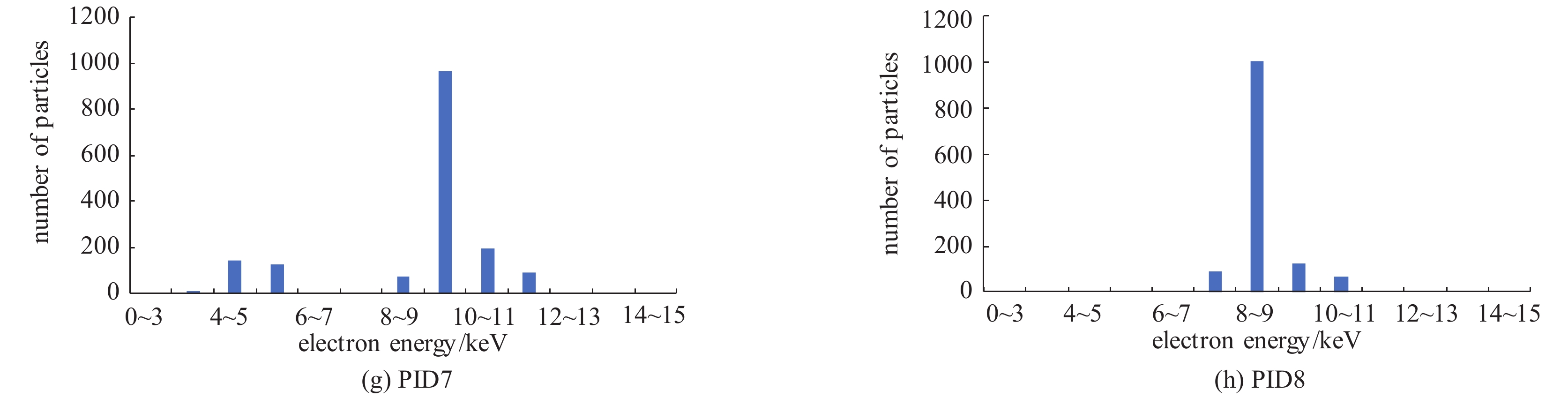
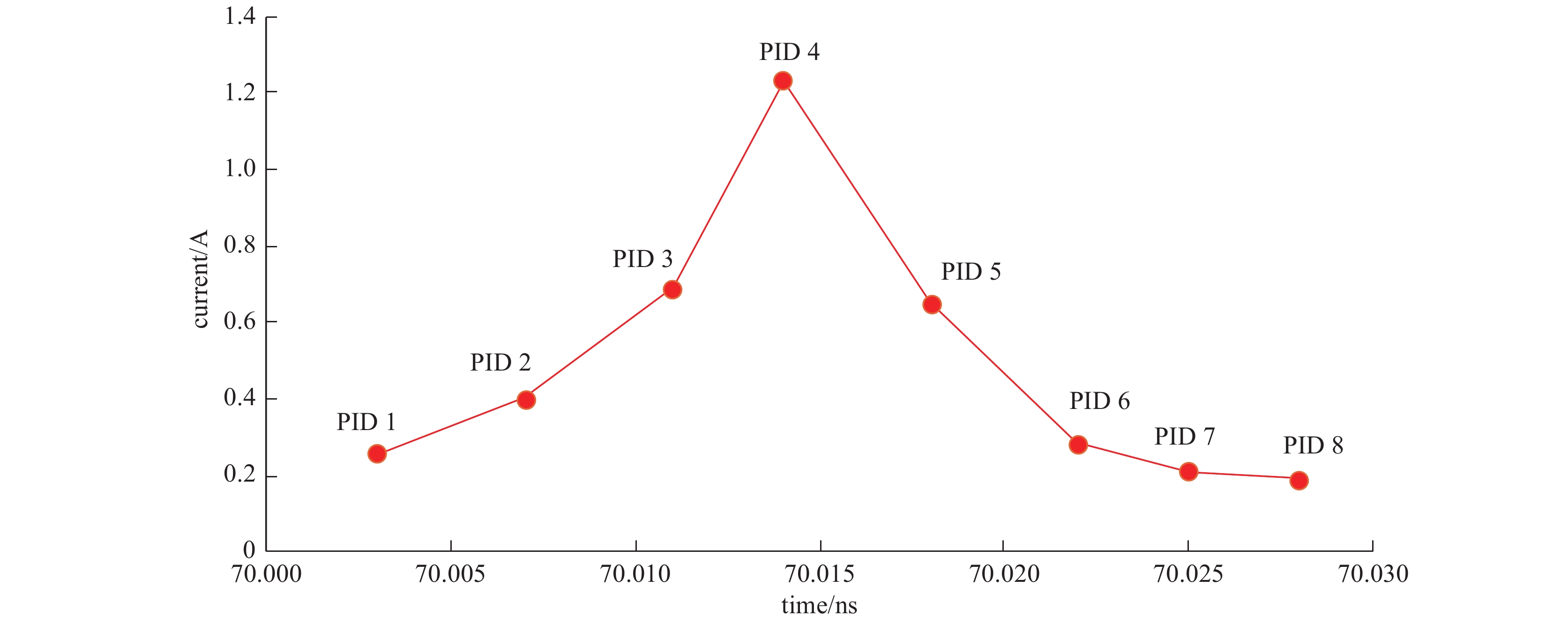
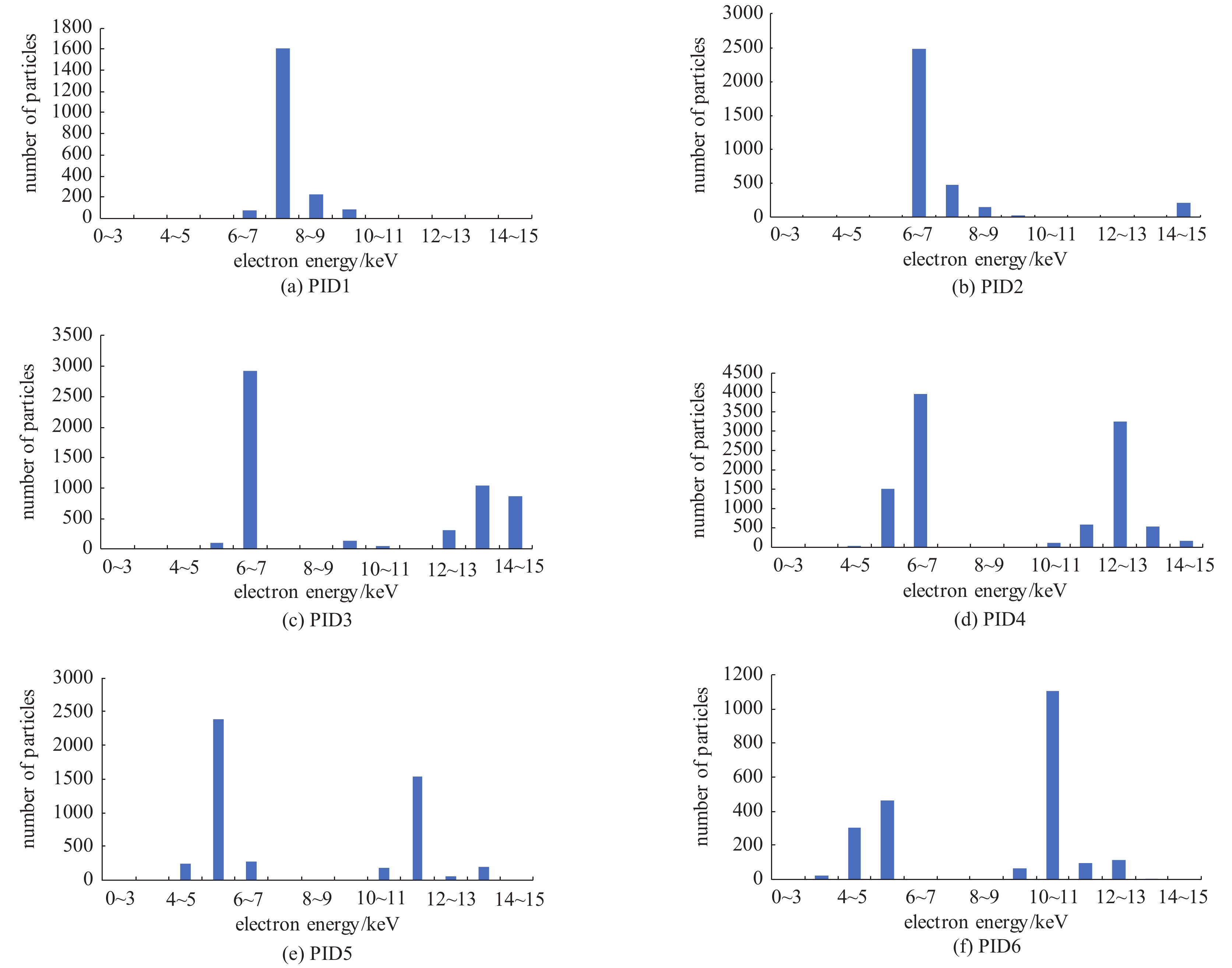
图 6 8等分时间点上携带不同能量的粒子数目统计图
Figure 6. Number of particles carrying different electron energy of point 1~8

图 8 未对收集极实施电压降时的电子轨迹
Figure 8. Electron beams trajectories in collector without voltage drop
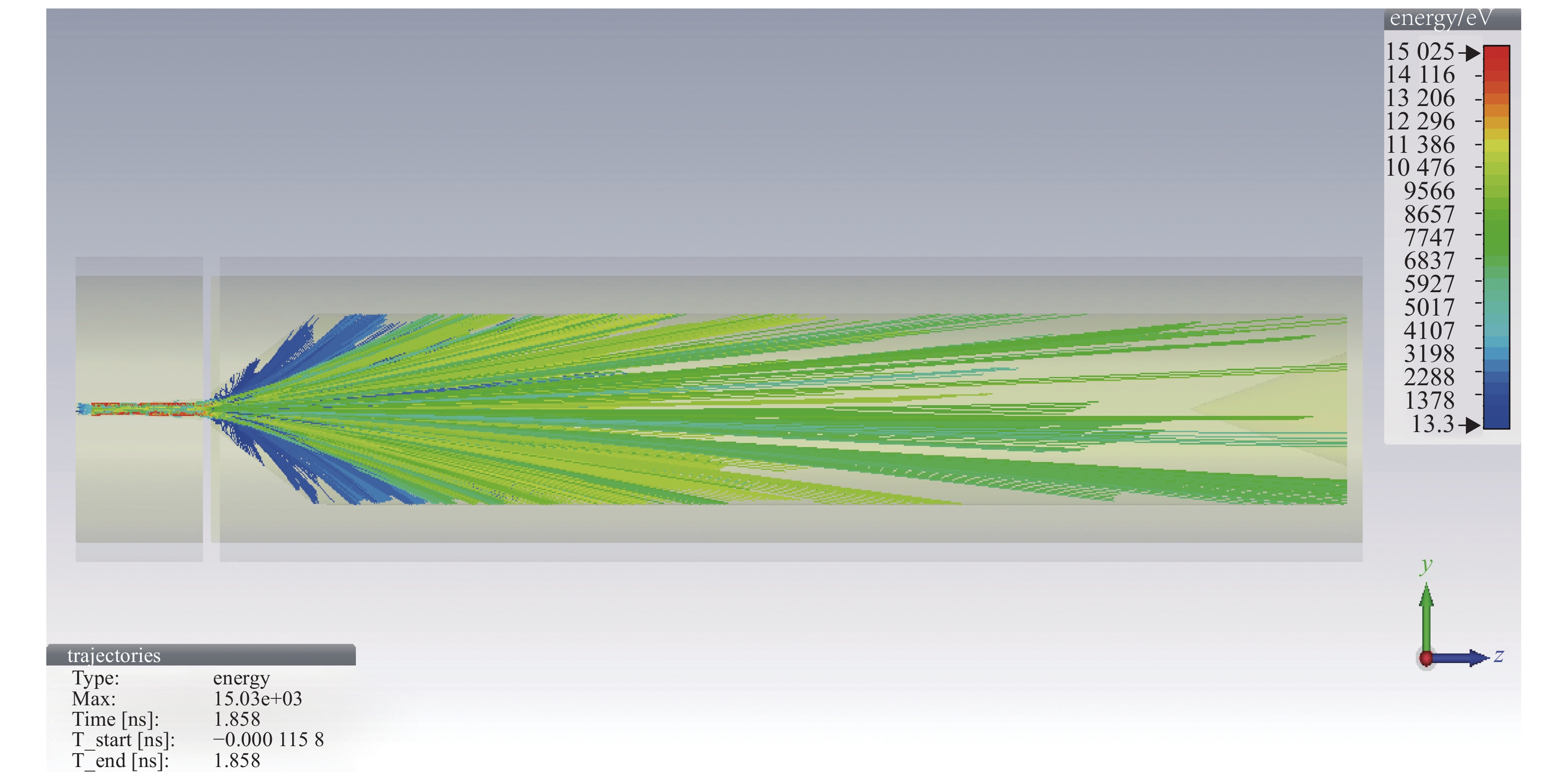
图 9 单级降压收集极电子轨迹
Figure 9. Electron beams trajectories in one-stage depressed collector
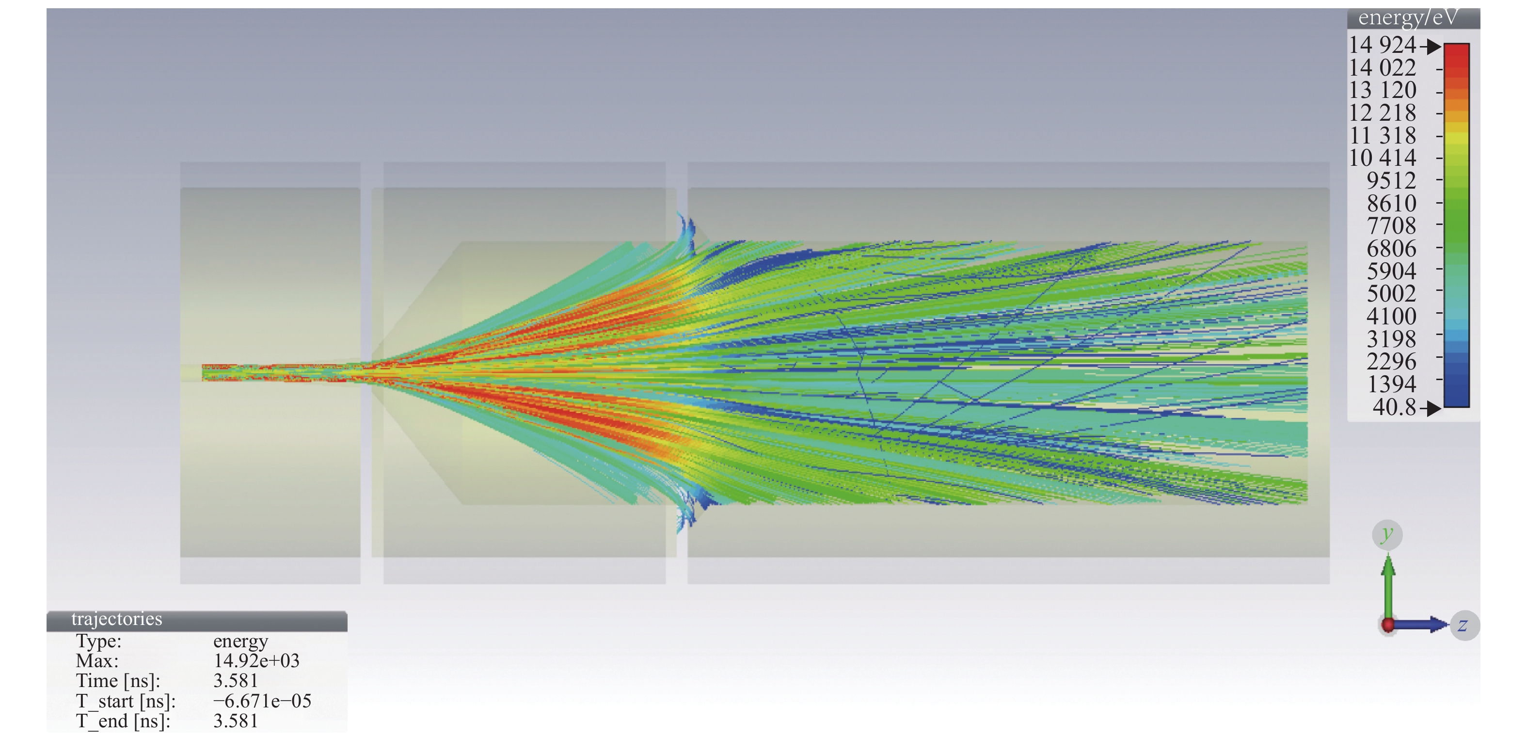
图 12 两级降压收集极内的电子轨迹
Figure 12. Electron beams trajectories in two-stage depressed collector
表 1 EIK的主要设计参数
Table 1. Main design parameters of the Ka-band extended interaction klystron(EIK)
frequency/GHz beam voltage/kV beam current/A output power of CW/kW efficiency/% gain/dB 35 10 0.49 1.35 27.5 54  下载: 导出CSV
表 2 部分废电子信息
Table 2. Information of part of waste electrons
x position/m y position/m z position/m $ {u}_{x} $ $ {u}_{y} $ $ {u}_{z} $ mass/kg charge/C macro particle charge/C time/s −1.23E−04 −2.81E−05 4.10E−02 −1.28E−03 2.68E−03 0.164 9.10E−31 −1.60E−19 −2.22E−16 2.50E−08 −1.12E−04 −5.39E−05 4.10E−02 −1.83E−03 2.25E−03 0.164 9.10E−31 −1.60E−19 −2.17E−16 2.50E−08 −1.18E−04 −3.67E−05 4.10E−02 9.95E−04 −4.13E−03 0.165 9.10E−31 −1.60E−19 −2.66E−16 2.50E−08 −2.46E−05 −2.33E−04 4.10E−02 −7.46E−03 −9.42E−03 0.164 9.10E−31 −1.60E−19 −1.87E−16 2.50E−08 −9.48E−05 −9.30E−05 4.10E−02 3.41E−03 −2.00E−03 0.164 9.10E−31 −1.60E−19 −2.39E−16 2.50E−08 −9.44E−05 −9.35E−05 4.10E−02 3.37E−03 −2.01E−03 0.164 9.10E−31 −1.60E−19 −2.39E−16 2.50E−08
下载: 导出CSV
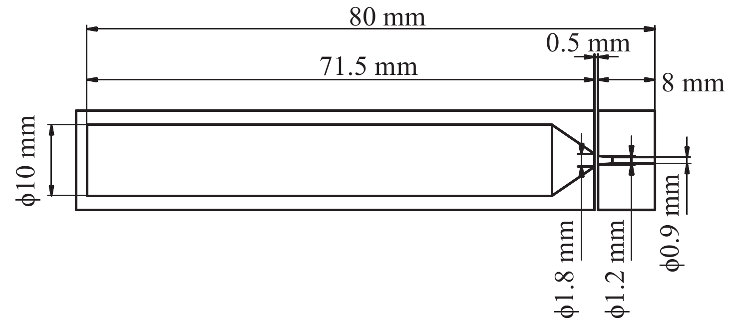
表 3 单级降压收集极的设计参数
Table 3. Design parameters of the one-stage depressed collector
drift length/mm drift entrance radius/mm drift exit radius/mm collector length/mm collector entrance radius/mm collector exit radius/mm 8 0.45 0.6 71.5 0.9 5
下载: 导出CSV
表 4 单级降压收集极的回收效率、回流率与压降的关系
Table 4. Relationship between recovery efficiency, reflux rate and voltage drop of the one-stage depressed collector
voltage/kV recovery efficiency/% electron reflux rate/% −3.0 26 0 −4.0 40 0 −4.1 41 0.02 −4.2 43 1.00 −4.3 44 1.05 −5.0 54 3.20 −6.0 68 4.60
下载: 导出CSV
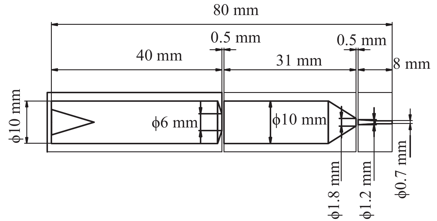
表 5 初始两级降压收集极的设计参数
Table 5. Design parameters of initial two-stage depressed collector
length/mm entrance radius/mm exit radius/mm drift one-stage collector two-stage collector drift one-stage collector two-stage collector drift one-stage collector two-stage collector 8 31 40 0.35 0.9 3 0.6 5 5
下载: 导出CSV
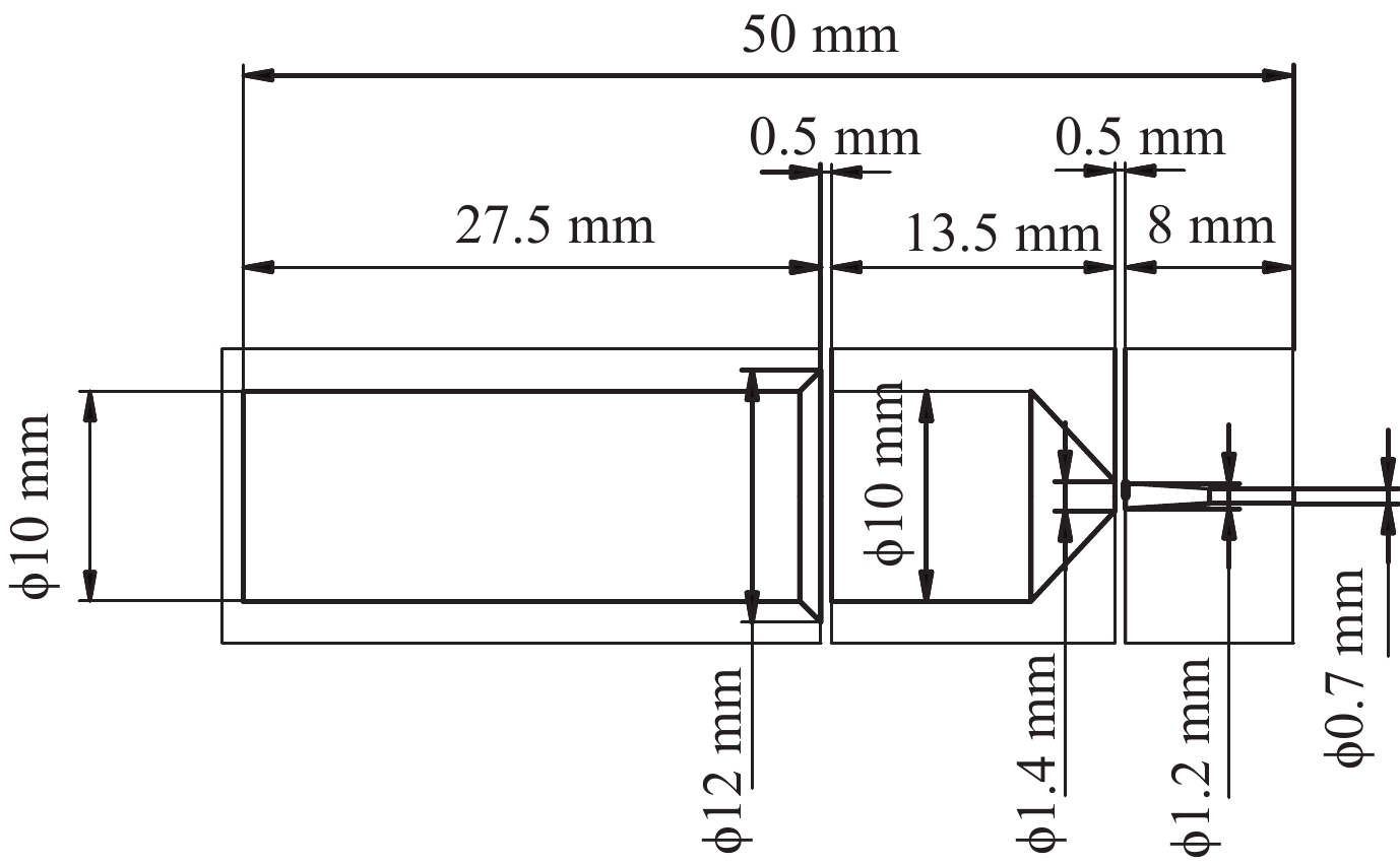
表 6 改进后的两级降压收集极设计参数
Table 6. Design parameters of improved two-stage depressed collector
length/mm entrance radius/mm exit radius/mm drift one-stage collector two-stage collector drift one-stage collector two-stage collector drift one-stage collector two-stage collector 8 13.5 27.5 0.35 0.7 6 0.6 5 5
下载: 导出CSV
表 7 优化的各级压降及回收效率
Table 7. Design parameters of improved two-stage depressed collector
voltage of the first stage/kV voltage of the second stage/kV recovery efficiency/% −4.1 −10 68.8 −3.7 −9 49.2 −3.0 −8 53.6 −2.1 −7 38.7 −1.5 −6 43.1 −0.6 −5 37.3 −4.0 −4 40.0
下载: 导出CSV
表 8 不同初始条件下的回收效率和整管效率
Table 8. Recovery efficiency and tube efficiency under different initial conditions
initial condition recovery efficiency/% tube efficiency/% PID 1 72.4 57.8 PID 2 70.9 56.1 PID 3 64.5 51.6 PID 4 68.8 54.8 PID 5 67.9 54.1 PID 6 66.1 52.8 PID 7 71.3 56.9 PID 8 72.8 58.2
下载: 导出CSV
-
[1] 洪伟, 余超, 陈继新, 等. 毫米波与太赫兹技术[J]. 中国科学: 信息科学, 2016, 46(8):1086-1107. (Hong Wei, Yu Chao, Chen Jixin, et al. Millimeter wave and terahertz technology[J]. Scientia Sinica Informationis, 2016, 46(8): 1086-1107 doi: 10.1360/N112016-00069 [2] 丁耀根. 功率速调管的技术现状和最新进展[J]. 真空电子技术, 2020(1):1-25. (Ding Yaogen. The technical status and latest progress of high-power klystron[J]. Vacuum Electronic, 2020(1): 1-25 [3] Srivastava V, Sinha A K, Josh S N, et al. Design of four-stage depressed collector for a high efficiency helix TWT[C]//Third IEEE International Vacuum Electronics Conference. 2002: 257-258. [4] Chodorow M, Wessel-Berg T. A high-efficiency klystron with distributed interaction[J]. IRE Trans Electron Devices, 1961, 8(1): 44-15. doi: 10.1109/T-ED.1961.14708 [5] 张长青, 阮存军, 王树忠, 等. 梯形结构高功率扩展互作用速调管[J]. 红外与毫米波学报, 2015, 34(3):307-313. (Zhang Changqing, Ruan Cunjun, Wang Shuzhong, et al. High-power extended-interaction klystron with ladder-type structure[J]. Journal of Infrared and Millimeter Waves, 2015, 34(3): 307-313 doi: 10.11972/j.issn.1001-9014.2015.03.010 [6] 丁耀根. 大功率速调管的设计制造与应用[M]. 北京: 国防工业出版社, 2010.Ding Yaogen. Design, manufacture and application of high-power klystrons[M]. Beijing: National Defense Industry Press, 2010 [7] 刘宇荣, 刘斌, 王大明. 大功率行波管两级降压收集极的设计[J]. 强激光与粒子束, 2017, 29:103002. (Liu Yurong, Liu Bin, Wang Daming. Design of two stage depressed collector for high-power traveling wave tube[J]. High Power Laser and Particle Beams, 2017, 29: 103002 doi: 10.11884/HPLPB201729.170144 [8] Gao Dongping, Ding Yaogen, Zhang Zhaochuan, et al. Design of a continuous wave Ka-band extended interaction klystron[C]//2014 IEEE International Vacuum Electronics Conference. 2014. [9] Ding Haibing, Tang Liang, Song Yihao, et al. Design of a Ka-band CW extended interaction klystron[C]//2018 IEEE International Vacuum Electronics Conference. 2018. [10] Gilmour A S. Klystron, traveling wave tubes, magnetrons, crossed-field amplifiers, and gyrotrons[M]. Beijing: National Defense Industry Press, 2012. [11] 寇建勇, 闫铁昌, 盛兴. 用Opera3D计算速调管多级降压收集极[J]. 真空电子技术, 2017(6):71-74. (Kou Jianyong, Yan Tiechang, Sheng Xing. Simulation of MDCs for klystrons using Opera 3D[J]. Vacuum Electronic, 2017(6): 71-74 [12] 刘明辉. 多级降压收集极的模拟与实验研究[D]. 成都: 电子科技大学, 2012: 10-25.Liu Minghui. Simulation and experimental study of multistage depressed collector[D]. Chengdu: University of Electronic Science and Technology, 2012: 10-25 [13] 郑志清, 罗勇, 蒋伟, 等. 回旋行波管收集极的热分析[J]. 强激光与粒子束, 2013, 25(3):721-726. (Zheng Zhiqing, Luo Yong, Jiang Wei, et al. Thermal analysis of gyrotron traveling-wave tube collector[J]. High Power Laser and Particle Beams, 2013, 25(3): 721-726 doi: 10.3788/HPLPB20132503.0721 [14] 白现臣, 杨建华, 张建德, 等. 电子束收集极对大间隙速调管输出腔效率的影响[J]. 强激光与粒子束, 2011, 23(6):1625-1628. (Bai Xianchen, Yang Jianhua, Zhang Jiande, et al. Influence of electron beam collector on output cavity efficiency of wide-gap klystron amplifier[J]. High Power Laser and Particle Beams, 2011, 23(6): 1625-1628 doi: 10.3788/HPLPB20112306.1625 [15] 耿志辉, 刘濮鲲, 粟亦农, 等. W波段连续波30 kW回旋振荡管高频系统和收集极的设计[J]. 强激光与粒子束, 2011, 23(11):3036-3038. (Geng Zhihui, Liu Pukun, Su Yinong, et al. Design of interaction circuit and collector for W-band continuous wave 30 kW gyrotron oscillator[J]. High Power Laser and Particle Beams, 2011, 23(11): 3036-3038 doi: 10.3788/HPLPB20112311.3036 -

 点击查看大图
计量
- 文章访问数: 2563
- HTML全文浏览量: 589
- PDF下载量: 108
- 被引次数: 0
